Toyota Corolla (E120) 2002–2008 Repair Manual / Diagnostics / Sfi system / Oxygen sensor circuit slow
response / Inspection procedure
Toyota Corolla (E120): Inspection procedure
Hint
: hand–held tester only: narrowing down the trouble area is possible by performing ”a/f control” active test (heated oxygen sensor or other trouble areas can be distinguished). Perform active test using hand–held tester (a/f control).
- Perform active test using the hand–held tester (a/f control).
Hint
: ”a/f control” is the active test which changes the injection volume to –12.5 % Or +25 %.
- Connect the hand–held tester to the dlc3 on the vehicle.
- Turn the ignition switch on.
- Warm up the engine by running the engine speed at 2,500 rpm for approximately 90 seconds.
- Select the item ”diagnosis / enhanced obd ii / active test / a/f control”.
- Perform ”a/f control” with the engine in an idle condition (press the right or left button).
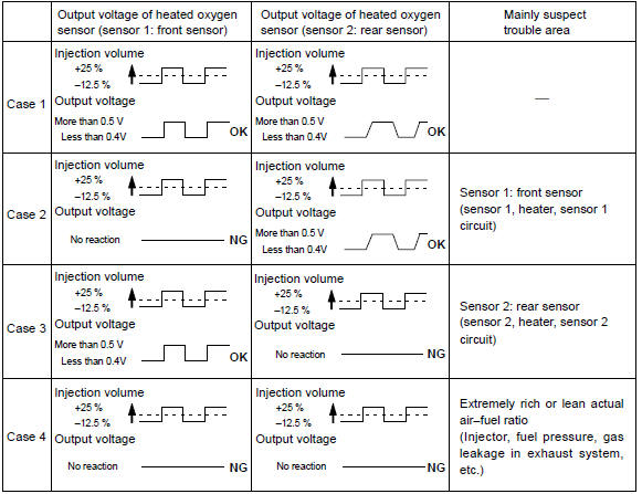
Result: heated oxygen sensor reacts in accordance with increase and decrease of injection volume +25 % rich output: more than 0.5 V, –12.5 % Lean output: less than 0.4 V
Notice
: there is a delay of few seconds in the sensor 1 (front sensor) output, and there is about 20 seconds delay at maximum in the sensor 2 (rear sensor)
The following of a/f control procedure enables the technician to check and graph the voltage outputs of both the heated oxygen sensors.
For displaying the graph indication, enter ”active test / a/f control / user data”, then select ”o2s b1s1 and o2s b1s2” by pressing ”yes” button and push ”enter” button before pressing ”f4” button.
Notice
: if the vehicle is short of fuel, the air–fuel ratio becomes lean and dtc p0133 will be recorded, and the mil then comes on. Hint
:
- if different dtcs related to different systems that have terminal e2 as the ground terminal are output simultaneously, terminal e2 may be open.
- Read freeze frame data using the hand-held tester or the obd ii scan tool. Freeze frame data records the engine conditions when a malfunction is detected. When troubleshooting, it is useful for determining whether the vehicle was running or stopped, the engine was warmed up or not, the air–fuel ratio was lean or rich, etc. At the time of the malfunction.
- A high heated oxygen sensor (sensor 1) voltage (0.5 V or more) could
be caused by a rich air fuel mixture.
Check for conditions that would cause the engine to run rich.
- A low heated oxygen sensor (sensor 1) voltage (0.4 V or less) could
be caused by a lean air fuel mixture.
Check for conditions that would cause the engine to run lean.
1 Check other dtc output(in addition to dtc p0133)
- Connect the hand–held tester or the obd ii scan tool to the dlc3.
- turn the ignition switch on and push the hand–held tester or the obd ii scan tool main switch on.
- read the dtcs using the hand–held tester or the obd ii scan tool.
Result
:

Hint
: if any other codes besides p0133 are output, perform the troubleshooting for those dtcs first.


2 Read value of hand–held tester or obd ii scan tool(heated oxygen sensor during idling)
- Connect the hand–held tester or the obd ii scan tool to the dlc3.
- start the engine and push the hand–held tester or the obd ii scan tool main switch on.
- select the item ”diagnosis / enhanced obd ii / data list / all / o2s b1s1”.
- warm up the heated oxygen sensor with the engine speed at 2,500 rpm for approximately 90 seconds.
- read the output voltage of the heated oxygen sensor during idling.
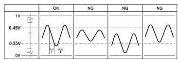
Heated oxygen sensor output voltage: alternates between less than 0.35 V and more than 0.45 V, and period of ”t” must exist less than 0.6 Sec. (See the following table).


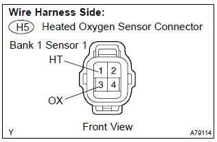
3 Inspect heated oxygen sensor(heater resistance)
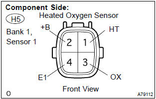
- Disconnect the h5 heated oxygen sensor connector.
- measure the resistance between the terminals of the heated oxygen sensor connector.
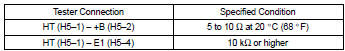
Standard:
- Reconnect the heated oxygen sensor connector.


4 Inspect efi relay
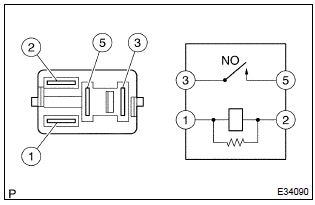
- Remove the efi relay from the engine room r/b.
- check for continuity in the efi relay.
Standard:
- Reinstall the efi relay.


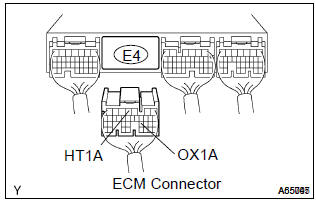
5 Check harness and connector(heated oxygen sensor – ecm)
- Disconnect the h5 heated oxygen sensor connector.
- disconnect the e4 ecm connector.
- check the resistance between the wire harness side connectors.
Standard (check for open):
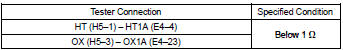
Standard (check for short):
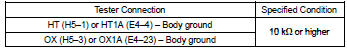
- Reconnect the ecm connector.
- reconnect the heated oxygen sensor connector.


6 Check air induction system
- Check the air induction system for vacuum leaks


7 Check fuel pressure
- Check the fuel pressure (high or low pressure).


8 Inspect fuel injector assy(injection and volume)


Replace heated oxygen sensor
9 Perform confirmation driving pattern
Hint
: clear all dtcs prior to performing the confirmation driving pattern.

10 Read output dtc(dtc p0133 is output again)
- Connect the hand–held tester or the obd ii scan tool to the dlc3.
- turn the ignition switch on and push the hand–held tester or the obd ii scan tool main switch on.
- read the dtcs using the hand–held tester or the obd ii scan tool.
Result:


Replace heated oxygen sensor


Other materials:
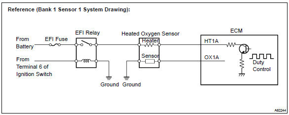
Circuit description
The vehicle speed sensor circuit is sent to cruise control ecu assy as a
vehicle speed signal. For each rotation
of the shaft, the vehicle speed sensor sends a signal through the combination
meter assembly to the
cruise control ecu assy (see the following chart). The cruise control ecu assy
...
Inspection procedure
1 Check front airbag sensor (lh) circuit (to b+)(airbag sensor assy
center – airbag sensor front lh)
Disconnect the negative (–) terminal cable from the battery,
and wait at least for 90 seconds.
disconnect the connectors between the airbag sensor
assy center and the airbag ...
Circuit description
The srs warning light is located on the combination meter.
When the srs is normal, the srs warning light lights up for approx. 6 Seconds
after the ignition switch is
turned from the lock position to on position, and then turns off automatically.
If there is a malfunction in the srs, the srs ...