Toyota Corolla (E120) 2002–2008 Repair Manual / Diagnostics / Sfi system / Oxygen sensor circuit malfunction / Circuit description
Toyota Corolla (E120): Circuit description
Refer to dtc p0130
|
Dtc no |
Dtc detection condition |
Trouble area |
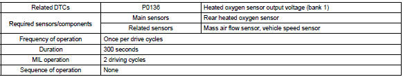
| P0136 | The following condition (a) or (b) continues for 300 seconds or
more:
|
|
Hint
: sensor 2 refers to the sensor farthest away from the engine assembly.
Monitor description
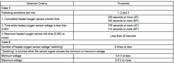
The heated oxygen sensor generates waveform of a voltage between 0 v and 1 v in response to the oxygen concentration in the exhaust gases. When the output voltage of the heated oxygen sensor is 0.5 V or more, the ecm judges that the air–fuel ratio is rich. When it is 0.40 V or less, the ecm judges that the air–fuel ratio is lean.
If the rear heated oxygen sensor output dose not change between rich and lean during ”stop and go” driving, the ecm interprets this as a malfunction in the rear heated oxygen sensor and sets a dtc. Also, if the sensor output remains at less than 0.05 V for more than 156 seconds when ecm monitored the heated oxygen sensor for 260 seconds while the air fuel feedback is being performed (the detecting condition differs depending on the type of vehicles), the ecm will interpret this as a fault. In either case, the ecm will turn on the mil and set a dtc.
Monitor strategy
Typical enabling conditions
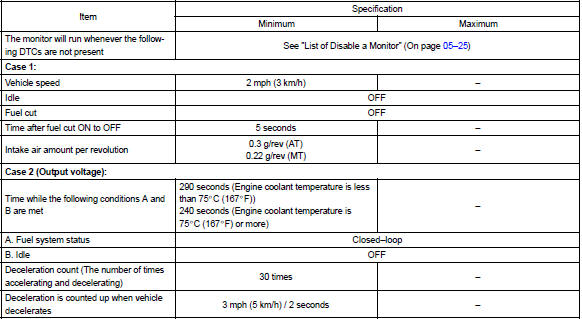
Typical malfunction thresholds
Component operating range

Monitor result (mode 06 data)
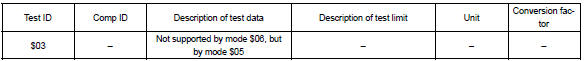
Refer to page 05–27 for detailed information on checking monitor status.
Wiring diagram
Refer to dtc p0130
Confirmation driving pattern
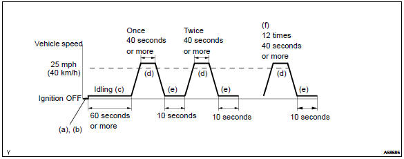
- Connect the hand–held tester to the dlc3.
- switch the hand–held tester from the normal mode to the check mode .
- start the engine and let it idle for 60 seconds or more.
- drive the vehicle at 25 mph (40 km/h) or more for 40 seconds or more.
- let the engine idle for 10 seconds or more.
- perform steps (d) and (e) 12 times.
Hint
: if a malfunction exists, the mil will be illuminated on the multi information display during step (f).
Notice
: if the conditions in this test are not strictly followed, a malfunction detection will not occur. If you do not have a hand–held tester, turn the ignition switch off after performing steps from (c) to (f), then perform steps from (c) to (f) again.


Other materials:
Overhaul
Hint:
installation is in the reverse order of the removal. But the
installation is indicated only when it has a
point.
In the rh side, work in the same procedure as in the lh side.
1. Remove front armrest assy lh
Using a screwdriver, remove the front armrest.
Hint:
tape the ...
Registering a new contact to the contact list
New contact data can be registered. Up to 4 numbers per person can be registered.
For PBAP compatible Bluetooth® phones, this function is available when “Automatic
Contact/History Transfer” is set to off.
1 Select “New Contact”.
2 Enter the name and select “OK”.
3 Enter the phone ...
Evap monitor (vacuum pressure monitor) (continued)
Preconditions
The monitor will not run unless:
mil is off.
Fuel level is approximately 1/2 to 3/4.
Altitude is 7800 feet (2400 m) or less.*
Engine coolant temperature (ect) is between 40°f and 95°f (4.4 °C and 35
°C).
Intake air temperature (iat) is between 40°f and 95 ...