Toyota Corolla (E120) 2002–2008 Repair Manual / Diagnostics / Sfi system / Oxygen sensor circuit slow
response / Circuit description
Toyota Corolla (E120): Circuit description
Refer to dtc p0130
|
Dtc no. |
Dtc detection condition |
Trouble area |
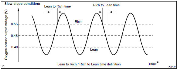
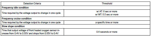
| P0133 | After engine has been warmed up, if response time that heated
oxygen sensor’s output voltage reaches from rich to lean. Or from lean to rich, is 0.6 Second or more during idling. (2 Trip detection logic) |
|
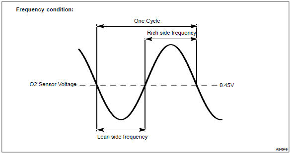
| If response time of heated oxygen sensor’s output voltage in one rich–lean cycle is 6 seconds or more during idling. (2 Trip detection logic) |
Hint
: sensor 1 refers to the sensor closest to the engine assembly.
Monitor description
The engine control module (ecm) uses the heated oxygen sensor information to regulate the air–fuel ratio close to a stoichiometric ratio. This maximizes the catalytic converter’s ability to purify the exhaust gases.
The sensor detects oxygen levels in the exhaust gas and sends this signal to the ecm.
The inner surface of the sensor element is exposed to the outside air. The outer surface of the sensor element is exposed to the exhaust gas. The sensor element is made of the platinum coated zirconia and includes an integrated heating element. The heated oxygen sensor has the characteristic whereby its output voltage change suddenly in the vicinity of the stoichiometric air–fuel ratio. The heated oxygen sensor generates waveform of a voltage between 0 v and 1 v in response to the oxygen concentration in exhaust gas.
When the output voltage of the heated oxygen sensor is 0.55 V or more, the ecm judges that the air–fuel ratio is rich. When it is 0.40 V or less, the ecm judges that the air–fuel ratio is lean.
The ecm monitors the response feature of the heated oxygen sensor. If the response time of the sensor output status change from rich to lean or vice versa becomes longer, the ecm interprets this as a malfunction in the heated oxygen sensor and sets a dtc.
Monitor strategy
Typical enabling condition
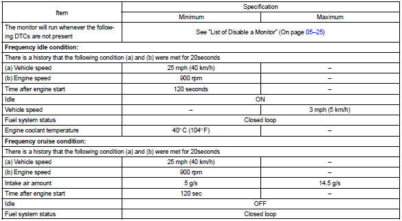
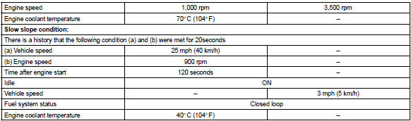
Typical malfunction thresholds
Component operating range

Wiring diagram
Refer to dtc p0130


Other materials:
When stopping the engine with the shift lever in a position other than P (vehicles
with a continuously variable transmission)
If the engine is stopped with the shift lever in a position other than P, the
engine switch will not be turned off but instead be turned to ACCESSORY mode. Perform
the following procedure to turn the switch off:
1 Check that the parking brake is set.
2 Shift the shift lever to P.
► Vehi ...
For safe driving
For safe driving, adjust the
seat and mirror to an appropriate
position before driving.
Correct driving posture
Adjust the angle of the seatback
so that you are sitting
straight up and so that you do
not have to lean forward to
steer.
Adjust the seat so that you
can depress the pedals fully ...
Skid control sensor
Replacement
Hint:
replace the rh side by the same procedure as the lh side.
1. Remove rear wheel
2. Remove rear brake drum sub–assy
3. Disconnect skid control sensor wire
Disconnect the skid control sensor wire connector from
the skid control sensor.
4. Remove rear axle hub & ...