Toyota Corolla (E120): Overhaul
Hint
: overhaul the rh side by the same procedure as the lh side.
1. Remove front wheel
2. Drain brake fluid
Notice
: wash the brake fluid off immediately if it comes into contact with any painted surface.
3. Remove front disc brake cylinder sub–assy
- Remove the union bolt and gasket from the disc brake cylinder, then disconnect the flexible hose.
Hint
: gasket has 2 types: 2–piece type and 1–piece type.
- Hold the cylinder slide pin and remove the 2 bolts.
4. Remove disc brake pad kit front (pad only)
- remove the 2 brake pads with anti–squeal shims.
- remove the anti–squeal shim no.1 And anti–squeal shim no.2 From each pad.
5. Remove front disc brake pad support plate
- remove the 2 front disc brake pad support plates from the cylinder mounting.
6. Remove front disc brake cylinder slide pin
- remove the 2 cylinder slide pins from the disc brake cylinder mounting.
7. Remove front disc brake cylinder mounting lh
- Remove the 2 bolts and disc brake cylinder mounting.
8. Remove front disc brake bush dust boot
- Place front disc brake cylinder mounting in vise.
- using a screwdriver and hammer, remove the 2 bush dust boots from the disc brake cylinder mounting.
9. Remove cylinder boot
- Using a screwdriver, remove the set ring and cylinder boot.
10. Remove front disc brake piston
- Place a piece of cloth or similar, between the piston and the disc brake cylinder.
- use compressed air to remove the piston from the disc brake cylinder.
Caution
: do not place your fingers in front of the piston when using compressed air.
Notice
: do not spatter the brake fluid.
11. Remove piston seal
- using a screwdriver, remove the piston seal from the disc brake cylinder.
12. Remove front disc brake bleeder plug
- remove the bleeder plug cap and bleeder plug from the disc brake cylinder.
13. Inspect brake cylinder and piston
- check the cylinder bore and piston for rust or scoring.
14. Inspect pad lining thickness
- Using a ruler, measure the pad lining thickness.
Standard thickness: 11.0 Mm (0.433 In.) Minimum thickness: 1.0 Mm (0.039 In.)
15. Inspect front disc brake pad support plate
- make sure that they have sufficient rebound, no deformation, cracks or wear, and have had all rust and dirt cleaned off.
16. Inspect disc thickness
- Using a micrometer, measure the disc thickness.
Standard thickness: 25.0 Mm (0.984 In.) Minimum thickness: 23.0 Mm (0.906 In.)
17. Remove front disc
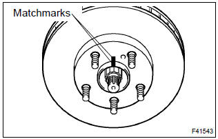
- Make matchmarks on the front disc and the axle hub.
- remove the front disc.
18. Install front disc
- aligning the matchmarks, install the front disc.
Hint
: select the installation position where the front disc has the minimum runout.
19. Inspect disc runout
- Temporarily fasten the disc with hub nuts.
Torque: 103 nvm (1,050 Kgf·cm, 76 ft·lbf)
- using a dial indicator, measure the disc runout 10 mm
(0.39 In.) Away from the outer edge of the disc.
Maximum disc runout: 0.05 Mm (0.0020 In.)
- if the disc runout is the maximum value or greater, check the bearing play in the axial direction and check the axle hub runout . If the bearing play and axle hub runout are normal, adjust the disc runout or grind it on a ”on–car” brake lathe.
20. Temporary tighten front disc brake bleeder plug
- temporarily tighten the bleeder plug, and install bleeder plug cap to the disc brake cylinder.
21. Install piston seal
- apply the lithium soap base glycol grease on a new piston seal.
- install the piston seal to the disc brake cylinder.
22. Install front disc brake piston
- apply the lithium soap base glycol grease on the piston.
- install the piston to the disc brake cylinder.
Notice
: do not screw the piston forcedly in the disc brake cylinder.
23. Install cylinder boot
- Apply the lithium soap base glycol grease to a new cylinder
boot. Install the cylinder boot to the disc brake cylinder.
Hint
: install the boot securely to the grooves of the cylinder and piston.
- using a screwdriver, install the set ring.
Notice
: do not damage the cylinder boot.
24. Install front disc brake bush dust boot
- Place front disc brake cylinder mounting in vise.
- apply the lithium soap base glycol grease to seal surface of 2 new bush dust boots.
- using a socket wrench (19 mm) and hammer, drive the 2 bush dust boots to the disc brake cylinder mounting.
25. Install front disc brake cylinder mounting lh
- install the disc brake cylinder mounting lh with the 2 bolts.
Torque: 106.8 Nvm (1,089 Kgf·cm, 79 ft·lbf)
26. Install front disc brake cylinder slide pin
- apply the lithium soap base glycol grease to the sliding part and the seal surface of the 2 cylinder slide pins.
- install the 2 cylinder slide pins to the disc brake cylinder mounting.
27. Install front disc brake pad support plate
- install the 2 front disc brake pad support plates to the cylinder mounting.
28. Install disc brake pad kit front (pad only)
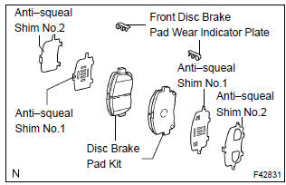
Notice
: if necessary, replace the anti–squeal shim kit when replacing the brake pad.
- apply disc brake grease to each anti–squeal shim no.1.
- install anti–squeal shims on each pad.
- install the pad wear indicator plate facing upward, and install each pad.
29. Install front disc brake cylinder sub–assy
- install the disc brake cylinder with the 2 bolts.
Torque: 34.3 Nvm (350 Kgf·cm, 25 ft·lbf)
- Install a new gasket and flexible hose with the union bolt.
Torque: 29 nvm (296 Kgf·cm, 21 ft·lbf)
Hint
:
- gasket has 2 types: 2–piece type and 1–piece type.
- Install the flexible hose lock securely in the lock hole in the disc brake cylinder.
30. Fill reservoir with brake fluid
31. Bleed master cylinder
sst 09023–00100
32. Bleed brake line
33. Check fluid level in reservoir
34. Check brake fluid leakage
35. Install front wheel
torque: 103 nvm (1,050 Kgf·cm, 76 ft·lbf)


Other materials:
Seat belt warning lamp for front passenger’s seat
does not flash
Wiring diagram
Inspection procedure
1 Inspect combination meter assy
Ground terminal c9–11 on the combination meter side.
check that the warning lightlights up.
Ok: warning light lights up.
2 Inspect passenger seat belt warning lamp assy
Ground terminal c9– ...
Front no.1 Speaker assy
Replacement
Hhint: components:
1. Remove front armrest assy lh
2. Remove power window regulator master switch assy (w/ power window)
3. Remove front armrest base panel upper lh (w/o power window)
4. Remove front door window regulator handle assy (w/o power window)
5. Remove front door lowe ...
Air bag sensor front lh
Components
Replacement
Hint: components:
1. Precaution
2. Disconnect battery negative terminal
3. Remove air bag sensor front lh
Disconnect the connector from the airbag sensor front
lh.
remove the 2 bolts and airbag sensor front lh.
4. Inspect air bag sensor front lh
...