Toyota Corolla (E120) 2002–2008 Repair Manual / Diagnostics / Sfi system / Random/multiple cylinder misfire
detected / Confirmation driving pattern
Toyota Corolla (E120): Confirmation driving pattern
- Connect the hand–held tester or the obd ii scan tool to the dlc3.
- record dtcs and the freeze frame data.
- set the check mode using the hand–held tester .
- read the value on the misfire counter for each cylinder when idling. If the value is displayed on the misfire counter, skip the following procedure of confirmation driving.
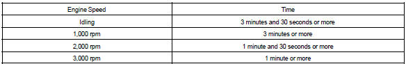
- drive the vehicle several times with the engine speed, load and its surrounding range shown with engine spd, calc load in the freeze frame data or misfire rpm, misfire load in the data list.
If you have no hand–held tester, turn the ignition switch off after the symptom is simulated once. Then repeat the simulation process again.
Hint
: do not turn the ignition switch off during the confirmation driving pattern. This switches the diagnosis system from the check mode to the normal mode, so all the dtcs and freeze frame data will be erased.
- Check whether there is misfire or not by monitoring dtc and the freeze frame data. After that, record them.
- turn the ignition switch off and wait for at least 5 seconds.


Other materials:
Problem symptoms table
Hint:
if a normal code is displayed during the dtc check but the trouble still occurs,
check the circuits for each
symptom in the order given in the charts on the following pages and proceed to
the page given for troubleshooting.
The matrix chart is divided into 3 chapters.
If the instruc ...
Rear view monitor system
The rear view monitor system assists the driver by displaying guide lines
and an image of the view behind the vehicle while backing up, for example while
parking.
The screen illustrations used in this text are intended as examples, and may
differ from the image that is actually displayed on t ...
Circuit description
A thermistor is built in the engine coolant temperature sensor and changes
the resistance value according
to the engine coolant temperature.
The structure of the sensor and connection to the ecm is the same as those of
the intake air temperature
sensor.
Hint:
if the ecm detects the dtc ...