Toyota Corolla (E120) 2002–2008 Repair Manual / Diagnostics / Combination meter / Malfunction in clock
Toyota Corolla (E120): Malfunction in clock
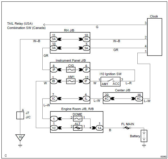
Wiring diagram
Inspection procedure
1 Inspect fuse
- Check the continuity in cig fuse.
- check the continuity in dome fuse.


2 Inspect harness or connector
- Check voltage.
- Remove the clock assy with connector still connected.
- Measure voltage between terminal 1 (+b) of clock assy connector and body ground.
Standard voltage: 10 – 14 v
- turn the ignition switch to acc.
- Measure voltage between terminal 4 (acc) of clock assy connector and body ground.
Standard voltage: 10 – 14 v
- check continuity.
- Check continuity between terminal 2 (e) of clock
assy connector and body ground.
Ok: continuity exists

Replace clock assy


Other materials:
Circuit description
Refer to dtc p0115
Dtc no.
Dtc detection condition
Trouble area
P0125
If the engine coolant temperature (ect) was less than –6.6 °C
(20 °F) when starting the engine, and 20 minutes after the engine
start, the ect sensor still indicates below 20 °C (68 ...
Replacement
Hint: components:
1. Discharge refrigerant from refrigeration system
sst 07110–58060 (07117–58080, 07117–58090, 07117–78050, 07117–88060,
07117–88070,
07117–88080)
2. Disconnect cooler refrigerant suction
hose no.1
Remove the bolt and disconnect the cooler refriger ...
Symptom simulation
Hint:
the most difficult case in troubleshooting is when no symptoms occurs. In such
cases, a thorough customer
problem analysis must be carried out. Then the same or similar conditions and
environment in which the
problem occurred in the customer’s vehicle should be simulated. No matter ho ...