
Toyota Corolla (E120) 2002–2008 Repair Manual / Diagnostics / Combination meter / The ambient temperature does not display
Toyota Corolla (E120): The ambient temperature does not display
Wiring diagram
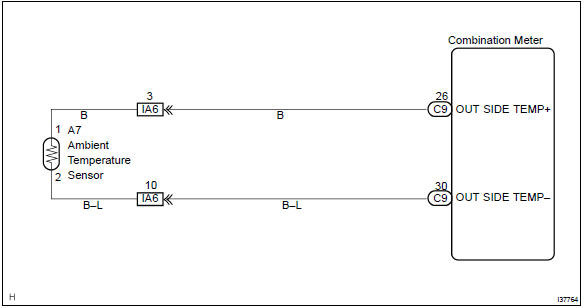
Inspection procedure
1 Inspect outer ambient temperature sensor
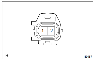
- Remove cooler (ambient temp. Sensor) thermistor.
- measure resistance between terminals 1 and 2 of cooler
(ambient temp. Sensor) thermistor connector at each temperature.
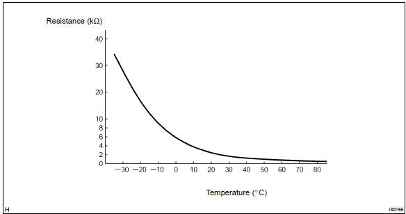
Resistance:
at 0 c (0 f) : 9.097 – 9.701 KΩ at 25 c (77 f) : 2.725 – 2.865 KΩ
Hint
: as the temperature increases, the resistance decreases.
Resistance:


2 Check harness and connector


Check and replace combination meter assy


Other materials:
Audio & visual system
Preparation
Sst
Recomended tools
Equipment
...
Refueling
Opening the fuel tank cap
Perform the following steps to open the fuel tank cap:
Before refueling the vehicle
● Close all the doors and windows, and turn the engine switch off.
● Confirm the type of fuel.
■Fuel types
Unleaded gasoline (Octane rating 87 [Research Octane Number ...
Inspection procedure
1 Check door lock
2 Check wire harness (tvip ecu door lock)
Disconnect the tvip ecu and door lock connectors.
check the continuity between the terminals of the tvip
ecu and door lock connectors, as shown in the illustration
and table.
Standard:
3 Check wire harness ...