Toyota Corolla (E120) 2002–2008 Repair Manual / Diagnostics / Power door lock control system / Key confinement prevention function does not work
properly (unlock warning switch circuit)
Toyota Corolla (E120): Key confinement prevention function does not work properly (unlock warning switch circuit)
Circuit description
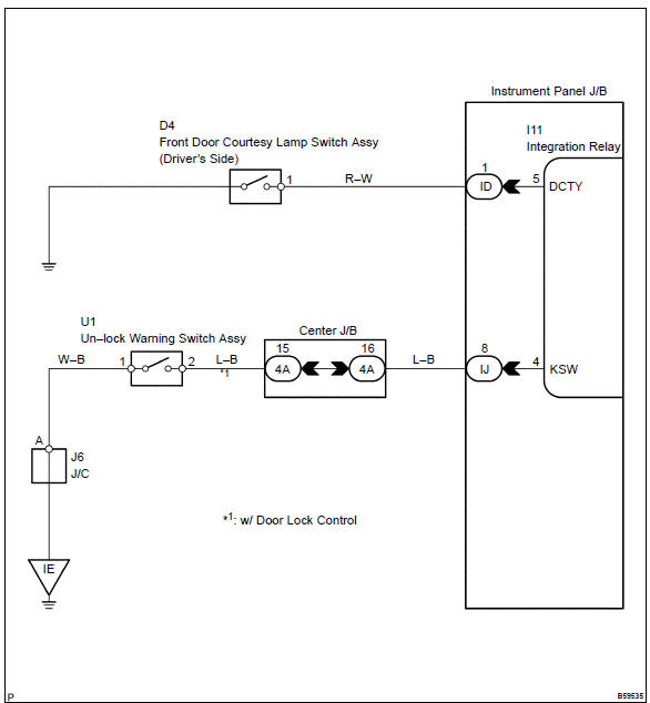
The unlock warning switch turns on when the key is inserted in the ignition key cylinder and the door courtesy switch turns on when the driver’s door is opened, and the integration relay monitors both switches conditions.
According to these switches conditions, the integration relay controls the door locking operation not to lock the doors while both switches are on, in order to prevent the key from being confined.
Wiring diagram
Inspection procedure
1 Inspect un–lock warning switch assy
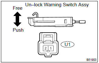
- Remove the un–lock warning switch assy.
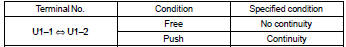
- inspect the un–lock warning switch assy continuity, as shown in the illustration and table.
Standard:


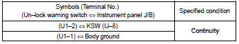
2 Check wire harness (un–lock warning switch instrument panel j/b)
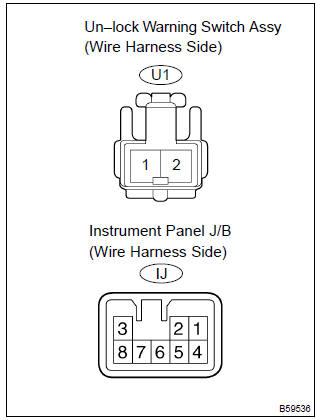
- Disconnect the un–lock warning switch assy and instrument panel j/b connectors.
- check the continuity between the terminals of the un–lock
warning switch assy and instrument panel j/b connectors,
as shown in the illustration and table.
Standard (check for open):

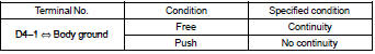
3 Inspect front door courtesy lamp switch assy (driver’s side)
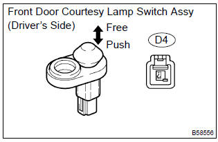
- Remove the courtesy lamp switch.
- inspect the courtesy lamp switch continuity, as shown in the illustration and table.
Standard:

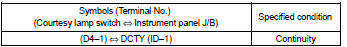
4 Check wire harness (front door courtesy lamp switch assy [driver’s side] instrument panel j/b)
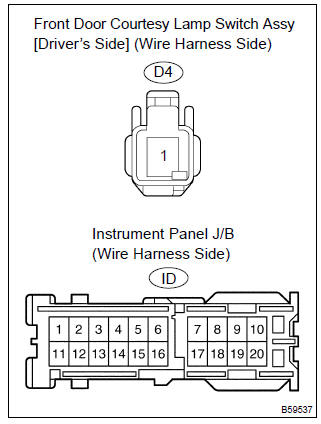
- Disconnect the courtesy lamp switch and instrument panel j/b connectors.
- check the continuity between the terminals of the courtesy lamp switch and instrument panel j/b connectors, as shown in the illustration and table.
Standard (check for open):

Replace integration relay


Other materials:
Seat heaters
Press the switch.
1 High temperature
2 Low temperature
The indicator light comes on when the switch is on.
■The seat heaters can be used when
► Vehicles without a smart key system
The engine switch is in the “ON” position.
►Vehicles with a smart key system
The engine ...
Circuit description
The side airbag sensor assy (lh) circuit consists of the diagnosis circuit
and lateral deceleration sensor, etc.
It receives signals from the lateral deceleration sensor, judges whether or not
the srs must be activated,
and detects diagnosis system malfunction.
Dtc b1141/33 is recorded wh ...
Replacement
1. Remove clutch start switch assy
disconnect the clutch start switch assy connector.
remove the nut and clutch start switch assy from the clutch pedal
support.
2. Install clutch start switch assy
install the clutch start switch assy with the nut.
Torque: 15.68 Nv ...