Toyota Corolla (E120) 2002–2008 Repair Manual / Diagnostics / Sfi system / Oxygen sensor heater control
circuit... / Inspection procedure
Toyota Corolla (E120): Inspection procedure
Hint
:
- if different dtcs related to different systems that have terminal e2 as the ground terminal are output simultaneously, terminal e2 may be open.
- Read freeze frame data using the hand-held tester or the obd ii scan tool. Freeze frame data records the engine conditions when a malfunction is detected. When troubleshooting, it is useful for determining whether the vehicle was running or stopped, the engine was warmed up or not, the air–fuel ratio was lean or rich, etc. At the time of the malfunction.
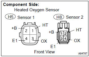
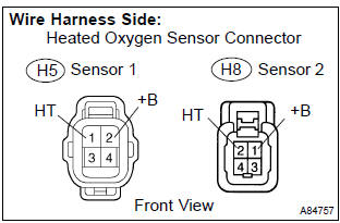
1 Inspect heated oxygen sensor(heater resistance)
- Disconnect the h5 or h8 heated oxygen sensor connector.
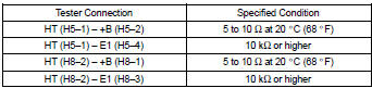
- measure the resistance between the terminals of the heated oxygen sensor connector.
Standard:
- Reconnect the heated oxygen sensor connector.


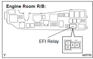
2 Inspect efi relay
- Remove the efi relay from the engine room r/b.
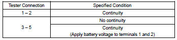
- check for continuity in the efi relay.
Standard:
- Reinstall the efi relay.


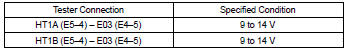
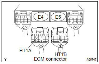
3 Inspect ecm(ht1a or ht1b voltage)
- Turn the ignition switch on.
- measure the voltage between the applicable terminals of the e4 and e5 ecm connectors.
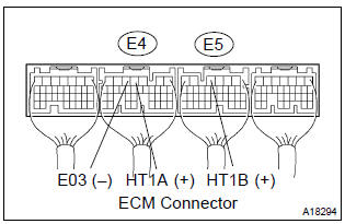
Standard:


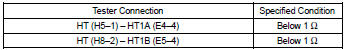
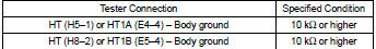
4 Check harness and connector(heated oxygen sensor – ecm, heated oxygen sensor – efi relay)
- Check the harness and connector between the ecm and heated oxygen sensor connectors.
- Disconnect the h5 or h8 heated oxygen sensor connector.
- Disconnect the e4 or e5 ecm connector.
- Check the resistance between the wire harness side connectors.
Standard (check for open):
Standard (check for short):
- Reconnect the heated oxygen sensor connector.
- Reconnect the ecm connector.
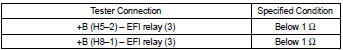
- check the harness and connector between the heated oxygen sensor connector and efi relay.
- Disconnect the h5 or h8 heated oxygen sensor connector.
- Remove the efi relay from the engine room r/b.
- Check the resistance between the wire harness side connectors.
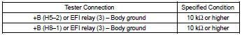
Standard (check for open):
Standard (check for short):
- Reconnect the heated oxygen sensor connector.
- Reinstall the efi relay.

Replace ecm


Other materials:
Engine mechanical
Preparation
Sst
Recomended tools
Ssm
Equipment
Exhaust
Preparation
Equipment
...
Cassette tape cannot be inserted or played
Wiring diagram
Inspection procedure
1 Check for any foreign object
Check for any foreign object.
Check that no foreign object or defect is detected in the cassette
tape player of radio receiver
assembly.
Standard: no foreign object and defect detected.
2 Check cassett ...
Starting system
Inspection
1. Inspect starter assy
Notice:
these tests must be performed within 3 to 5 seconds to
prevent burnout of the coil.
perform the pull–in test.
Remove the nut, then disconnect the lead wire from
terminal c.
Connect the battery to the starter repai ...