Toyota Corolla (E120) 2002–2008 Repair Manual / Diagnostics / Sfi system / Oxygen sensor heater control
circuit... / Circuit description
Toyota Corolla (E120): Circuit description
Refer to dtc p0130
Hint
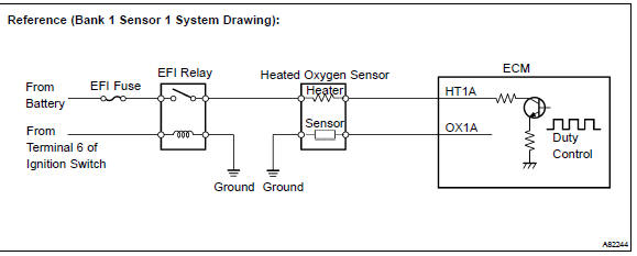
: the ecm provides a pulse width modulated control circuit to adjust current through the heater. The heated oxygen sensor heater circuit uses a relay on the b+ side of the circuit.
Monitor description
The ecm uses the heated oxygen sensor information to regulate the air–fuel ratio close to a stoichiometric ratio. This maximizes the catalytic converter’s ability to purify the exhaust gas. The sensor detects oxygen levels in the exhaust gas and sends this signal to the ecm.
The inner surface of the sensor element is exposed to the outside air. The outer surface of the sensor element is exposed to the exhaust gas. The sensor element is made of the platinum coated zirconia and includes an integrated heating element. The heated oxygen sensor has the characteristic whereby its output voltage change suddenly in the vicinity of the stoichiometric air–fuel ratio. When heated, the sensor becomes very efficient. If the temperature of the exhaust is low, the sensor will not generate useful voltage signals without supplemental heating. The ecm regulates the supplemental heating using a duty–cycle approach to regulate the average current in the heater element. If the heater current is out of the normal range, the sensor’s output signals will be inaccurate and the ecm cannot regulate the air–fuel ratio properly. When the heater current is out of the normal operating range, the ecm interprets this as a malfunction and sets a dtc.
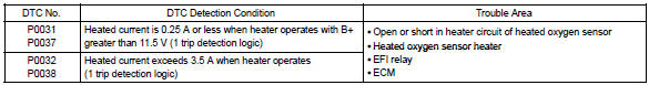
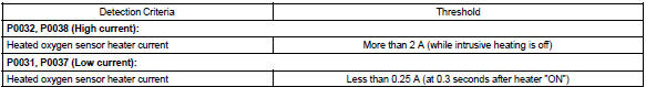
Example: the ecm will set a high current dtc if the current in the sensor is more than 2 a when the heater is off.
Similarly, the ecm will set a low current dtc if the current is less than 0.25 A when the heater is on.
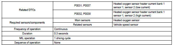
Monitor strategy
Typical enabling conditions
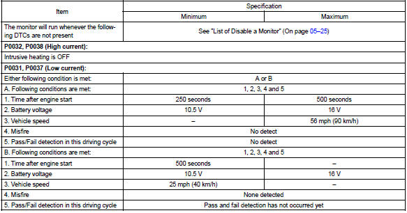
Typical malfunction thresholds
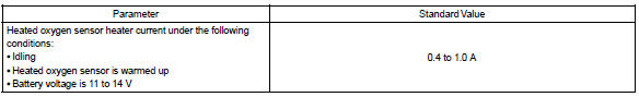
Component operating range
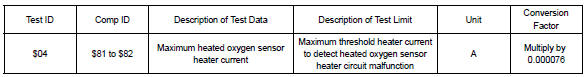
Monitor result (mode 06 data)
Refer to page 05–27 for detailed information on checking monitor status.
Wiring diagram
Refer to dtc p0130


Other materials:
Changing the passkey
1 Select “Passkey” using . 2 Input
a 4 to 8-digit passkey using .
Input the number 1 digit at a time.
3 When the entire number to be registered as a passkey has been input, press
again.
If the passkey to be registered has 8 digits, pressing
again is not necessary. ...
Inspection procedure
Hint:
perform the troubleshooting of dtc p0335 first. If no trouble is
found, troubleshoot the engine mechanical
systems.
Read freeze frame data using the hand-held tester or the obd ii scan tool.
Freeze frame data records
the engine conditions when a malfunction is detected. When tr ...
Overhaul
Hint: components:
1. Remove rear wheel
2. Remove spare wheel cover assy
3. Remove rear floor finish plate
4. Remove luggage compartment trim cover inner lh
5. Remove rear shock absorber with coil spring
Support the rear axle beam with jack.
Remove the 2 nuts and bolt.
...