Toyota Corolla (E120) 2002–2008 Repair Manual / Diagnostics / Sfi system / Random/multiple cylinder misfire
detected / Inspection procedure
Toyota Corolla (E120): Inspection procedure
Hint
:
- if dtcs besides misfire are memorized simultaneously, first perform the troubleshooting for them.
- Read freeze frame data using the hand-held tester or the obd ii scan tool. Freeze frame data records the engine conditions when a malfunction is detected. When troubleshooting, it is useful for determining whether the vehicle was running or stopped, the engine was warmed up or not, the air–fuel ratio was lean or rich, etc. At the time of the malfunction.
- If the misfire does not occur when the vehicle is brought to the workshop, the misfire can be confirmed by reproducing the condition of the freeze frame data. After finishing the repair, confirm that there is no misfire (see confirmation driving pattern).
- When either of short ft #1 or long ft #1 in the freeze frame data is
over the range of ±20 %,
there is a possibility that the air–fuel ratio is inclining either to rich
(–20 % or less) or lean (+20 %
or more).
When coolant temp in the freeze frame data is less than 80°c (176°f), there is a possibility of misfire only during engine warm up.
- If the misfire cannot be reproduced, the reason may be because of the driving the vehicle with lack of fuel, the use of improper fuel, a stain on the ignition plug, etc.
- Be sure to check the value on the misfire counter after the repair.
1 Check other dtc output(in addition to misfire dtcs)
- Connect the hand–held tester or the obd ii scan tool to the dlc3.
- turn the ignition switch on and push the hand–held tester or the obd ii scan tool main switch on.
- select the item ”diagnosis / enhanced obd ii / dtc info / current codes”.
- read the dtcs.
Result:

Hint
: if any other codes besides p0300, p0301, p0302, p0303 or p0304 are output, perform the troubleshooting for those dtcs first.


2 Check wire harness, connector and vacuum hose in engine room
- Check the connection conditions of the wire harness and connector.
- check the vacuum hose piping for disconnection and break.


3 Check connection of pcv hose


4 Read value of hand–held tester or obd ii scan tool(number of misfire)
- Connect the hand–held tester or the obd ii scan tool to the dlc3.
- turn the ignition switch on and push the hand–held tester or the obd ii scan tool main switch on.
- start the engine.
- select the item ”diagnosis / enhanced obd ii / data list / all / cyl#1 – cyl#4”.
- read the number of misfire on the hand–held tester or the obd ii scan tool.
Hint
: when a misfire is not reproduced, be sure to branch below based on the stored dtc. Result:


5 Check spark plug and spark of misfiring cylinder
- Remove the ignition coil assembly.
- remove the spark plug.
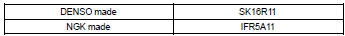
- check the spark plug type.
Recommended spark plug:
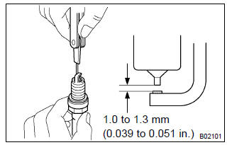
- Check the spark plug electrode gap.
Electrode gap: 1.0 To 1.3 Mm (0.039 To 0.051 In.) Notice
: if adjusting the gap of a new spark plug, bend only the base of the ground electrode. Do not touch the tip. Never attempt to adjust the gap on a used plug.
- check the electrode for carbon deposits.
- perform a spark test.
Caution
: absolutely disconnect the each injector connectors.
Notice
: do not crank the engine for more than 5 seconds at a time.
- Install the spark plug to the ignition coil, and connect the ignition coil connector.
- Disconnect the injector connector.
- Ground the spark plug.
- Check if spark occurs while the engine is being cranked.
Standard: spark jumps across electrode gap.
- reinstall the spark plug.
- reinstall the ignition coil assy.


6 Change normal spark plug and check spark of misfiring cylinder
- Change to the normal spark plug.
- perform a spark test.
Caution
: absolutely disconnect each injector connector.
Notice
: do not crank the engine for more than 5 seconds at a time.
- Install the spark plug to the ignition coil, and connect the ignition coil connector.
- Disconnect the injector connector.
- Ground the spark plug.
- Check if spark occurs while the engine is being cranked.
Standard: spark jumps across electrode gap.


7 Check harness and connector of misfiring cylinder(ignition coil – ecm)
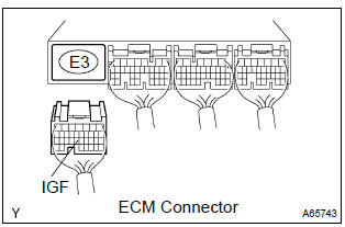
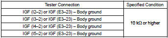
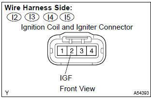
- Check the harness and connector between the ignition coil and ecm (igf terminal) connectors
- disconnect the i2, i3, i4 or i5 ignition coil and igniter connector.
- Disconnect the ecm e3 connector.
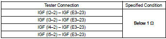
- Check the resistance between the wire harness side connectors.
Standard (check for open):
Standard (check for short):
- Reconnect the ecm connector.
- Reconnect the ignition coil and igniter connector.
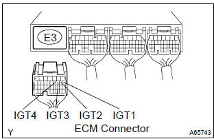
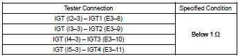
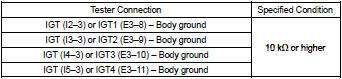
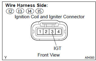
- check the harness and connector between the ignition coil and ecm (igt terminal) connectors
- disconnect the i2, i3, i4 or i5 ignition coil and igniter connector.
- Disconnect the ecm e3 connector.
- Check the resistance between the wire harness side connectors.
Standard (check for open):
Standard (check for short):
- Reconnect the ecm connector.
- Reconnect the ignition coil and igniter connector.


Repair or replace harness or connector
8 Inspect ecm terminal of misfiring cylinder(#10, #20, #30 or #40 voltage)
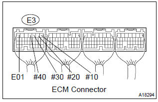
- Turn the ignition switch on.
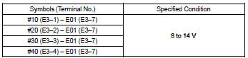
- measure the voltage between the terminals of the e3 ecm connector.
Standard:


9 Inspect fuel injector resistance of misfiring cylinder


10 Check harness and connector of misfiring cylinder(injector – ecm, injector – ignition switch)
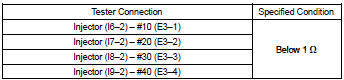
- Check the harness and connector between the injector connector and ecm connector.
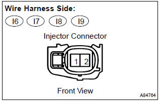
- Disconnect the i6, i7, i8 or i9 injector connector.
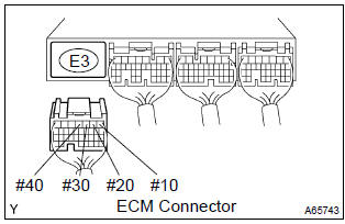
- Disconnect the e3 ecm connector.
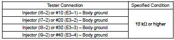
- Measure the resistance between the wire harness side connectors.
Standard (check for open):
Standard (check for short):
- Reconnect the ecm connector.
- Reconnect the iinjector connector.
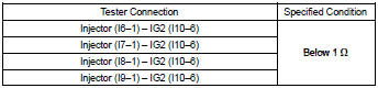
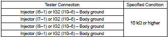
- check the harness and connector between the injector connector and ignition switch connector.
- Disconnect the i6, i7, i8 or i9 injector connector.
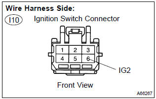
- Disconnect the i10 ignition switch connector.
- Measure the resistance between the wire harness side connectors.
Standard (check for open):
Standard (check for short):
- Reconnect the ignition switch connector.
- Reconnect the injector connector.

11 Inspect fuel injector injection and volume of misfiring cylinder


12 Check cylinder compression pressure of misfiring cylinder

13 Check valve clearance of misfiring cylinder

14 Switch step by number of misfire cylinder(refer result of step 4)
Hint
:
- if the result of step 4 is ”1 or 2 cylinders” proceed to a.
- If the result of step 4 is ”more than 3 cylinders” proceed to b.


15 Check valve timing(check for looseness or a jumped tooth of the timing chain)
16 Check fuel pressure
17 Read value of hand–held tester or obd ii scan tool(intake air temperature and mass air flow rate)
- Connect the hand–held tester or the obd ii scan tool to the dlc3.
- turn the ignition switch on.
- check the intake air temperature.
- Select the item ”diagnosis / enhanced obd ii / data list / all /
intake air” and read
its value displayed on the hand–held tester or the obd ii scan tool.
Temperature: equivalent to ambient temperature
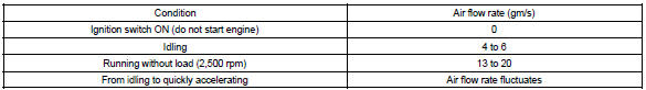
- check the air flow rate.
- Select the item ”diagnosis / enhanced obd ii / data list / all /
maf” and read its value
displayed on the hand–held tester or the obd ii scan tool.
Standard:


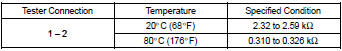
18 Inspect engine coolant temperature sensor(resistance)
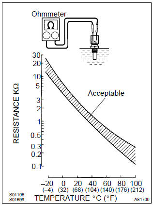
- Remove the engine coolant temperature sensor.
- measure the resistance between the terminals of the engine coolant temperature sensor.
Standard:
Notice
: if you checking the engine coolant temperature sensor in water, be careful not to allow water to go into the terminals.
After checking, dry the sensor.
Hint
: alternate procedure: connect an ohmmeter to the installed engine coolant temperature sensor and read the resistance. Use an infrared thermometer to measure the engine temperature in the immediate vicinity of the sensor. Compare these values to the resistance/temperature graph. Change the engine temperature (warm up or allow to cool down) and repeat the test.

19 Switch step by number of misfire cylinder(refer result of step 4)
Hint
:
- if the result of step 4 is ”1 or 2 cylinders” proceed to a.
- If the result of step 4 is ”more than 3 cylinders” proceed to b.


Check for intermittent problems


Other materials:
Circuit description
Refer to dtcs p0100
Dtc no.
Dtc detection condition
Trouble area
P0101
After engine is warmed up, conditions (a) to (d) continue for
more than 10 seconds (2 trip detection logic):
engine speed less than 900 rpm
throttle valve fully closed
&nbs ...
Circuit description
The p squib (2nd step) circuit consists of the airbag sensor assy center and
instrument panel passenger
airbag assy.
It causes the srs to deploy when the srs deployment conditions are satisfied.
Dtc b1185/57 is recorded when a short is detected in the p squib (2nd step)
circuit.
Wiri ...
Inspection
1. Inspect inner rear view mirror assy
Inspect the electro chromic inner mirror operation.
Connect the positive (+) lead from the battery to terminal
1 and negative (–) lead to terminal 2.
) Attach black colored tape to the forward sensor to
prevent it from sensing.
&nb ...