Toyota Corolla (E120) 2002–2008 Repair Manual / Diagnostics / Audio system / Sound quality is bad in all modes (volume is too low)
Toyota Corolla (E120): Sound quality is bad in all modes (volume is too low)
Wiring diagram
Inspection procedure
1 Adjust sound quality
- Adjust the sound quality.
- Operate the radio receiver assy to adjust the sound quality.
Standard: malfunction disappear.


2 Compare it with another car of same model
- Compare it with another vehicle of the same model.
- Compare with the vehicle of the same type which does not have a
trouble to see if there is any
difference in the condition of trouble occurrence.
Standard: no difference found.


3 Check harness and connector(between radio receiver assy and speaker)

4 Inspect front no.1 Speaker assy
- Preparation for check
- disconnect the connector of the speaker.
- resistance check
- check the resistance between the terminals of the speaker.
Notice
: the speaker should not be removed for checking.
Standard value: 4 Ω


5 Inspect front no.2 Speaker assy
- Check that malfunction disappear when a known good speaker is installed.
Standard: malfunction disappear.
Hint
: connect the all connectors of speakers.


6 Inspect rear speaker assy
- Preparation for check
- disconnect the connector of the speaker.
- resistance check
- check the resistance between the terminals of the speaker.
Notice
: the speaker should not be removed for checking.
Standard value: 6 Ω


7 Inspect radio receiver assy(+b, acc, gnd)
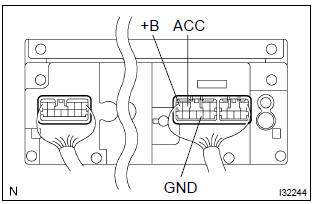
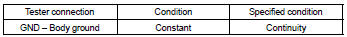
- Check that the continuity between terminals at each condition, as shown in the chart.
Standard:
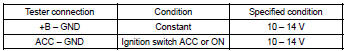
- Check that the voltage between terminals at each condition, as shown in the chart.
Standard:

Repair or replace harness or connector


Other materials:
Vehicle identification
■ Vehicle identification number
The vehicle identification number (VIN) is the legal identifier for your vehicle.
This is the primary identification number for your Toyota. It is used in registering
the ownership of your vehicle.
This number is stamped on the top left of the instrument p ...
Circuit description
The airbag sensor assy center consists of a airbag sensor assy center, safing
sensor, drive circuit, diagnosis
circuit and ignition control, etc.
It receives signals from the airbag sensor, judges whether or not the srs must
be activated, and detects
diagnosis system malfunction.
Dtc b11 ...
Types of child restraints
Child restraint systems are classified into the following 3 types according to
the age and size of the child:
► Rear facing - Infant seat/convertible seat
► Forward facing - Convertible seat
► Booster seat
■Selecting an appropriate child restraint system
●U ...