Toyota Corolla (E120) 2002–2008 Repair Manual / Diagnostics / Sfi system / Vehicle speed sensor ”a” / Circuit description
Toyota Corolla (E120): Circuit description
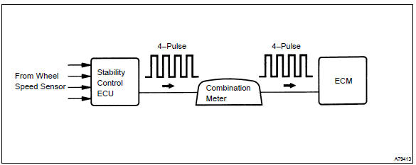
The vehicle equipped with abs detects a vehicle speed using the stability control ecu and wheel speed sensor. This sensor monitors a wheel rotation speed and sends the signal to the ecu.
The stability control ecu converts these wheel speed signals into a 4–pulse signal and outputs it to the ecm via the combination meter.
The ecm determines the vehicle speed based on the frequency of these pulse signals.
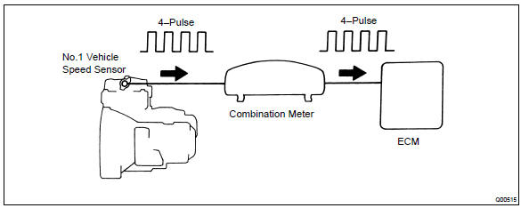
In the vehicle without abs, the no. 1 Vehicle speed sensor outputs a 4–pulse signal for every revolution of the rotor shaft, which is rotated by the transmission output shaft via the driven gear. After this signal is converted into a more precise rectangular waveform by the waveform shaping circuit inside the combination meter, it is then transmitted to the ecm. The ecm determines the vehicle speed based on the frequency of these pulse signal.
W/ abs:
W/o abs:
Monitor description
Equipped with abs:
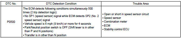
the ecm assumes that the vehicle is driven when the rpm of the transmission counter gear indicates more than 300 rpm and it has been over 30 seconds since the park/neutral position switch was turned off. If there is no signal from the vehicle speed sensor with these conditions satisfied, the ecm concludes that there is a fault in the vehicle speed sensor. The ecm will turn on the mil and a dtc is set.
Not equipped with abs:
the ecm assumes that the vehicle is driven when the park/neutral position switch is off and it has been over 4 seconds since the actual vehicle speed was 9 km/h or more.
If there is no signal from the vehicle speed sensor with these conditions satisfied, the ecm concludes that there is a fault in the vehicle speed sensor. The ecm will turn on the mil and a dtc is set.
Monitor strategy
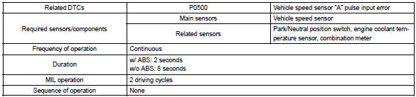
Typical enabling conditions
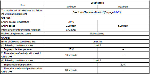
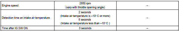
Typical malfunction thresholds

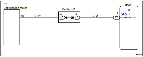
Wiring diagram


Other materials:
Shift solenoid ”a” performance
(shift solenoid valve s1)
Dtc p0751 shift solenoid ”a” performance
(shift solenoid valve s1)
System description
The ecm uses signals from the vehicle speed sensor and crankshaft position
sensor to detect the actual
gear position (1st, 2nd, 3rd or o/d gear).
Then the ecm compares the actual gear with the shift sc ...
Circuit description
Refer to dtc p0010
Dtc no.
Dtc detection condition
Trouble area
P0011
Condition (a) or (b) continues after engine is warmed up and
engine speed at 550 to 4,000 rpm (problem of the advanced
ocv):
valve timing does not change from current valve tim ...
Engine immobilizer system
The vehicle’s keys have built-in transponder chips that prevent the engine
from starting if a key has not been previously registered in the vehicle’s on-board
computer.
Never leave the keys inside the vehicle when you leave the vehicle.
Vehicles without a smart key system: The indicator li ...