Toyota Corolla (E120) 2002–2008 Repair Manual / Diagnostics / Audio system / Cassette tape cannot be inserted or played
Toyota Corolla (E120): Cassette tape cannot be inserted or played
Wiring diagram
Inspection procedure
1 Check for any foreign object
- Check for any foreign object.
- Check that no foreign object or defect is detected in the cassette
tape player of radio receiver
assembly.
Standard: no foreign object and defect detected.


2 Check cassette tape
- Check the cassette tape.
- Check that the cassette tape is a normal tape to which music or
voice is recorded.
Standard: proper cassette tape to which music or voice is recorded.


3 Replace cassette tape with another and recheck
- Replace the cassette tape with another and recheck.
- Replace the faulty cassette tape with the normal one to see if the
same trouble occurs again.
Standard: the function is recovered to be normal.


4 Check if radio auto–search functions properly
- Check if the radio auto–search functions properly.
- Perform the auto–search of the radio and check that the operation
is normal.
Standard: the operation returns to be normal.

5 Inspect radio receiver assy(+b, acc, gnd)
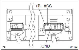
- Check that the continuity between terminals at each condition, as shown in the chart.
Standard:

- Check that the voltage between terminals at each condition, as shown in the chart.
Standard:
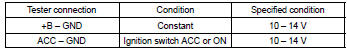

Repair or replace harness or connector


Other materials:
Fuel
Preparation
Sst
Recomended tools
Ssm
Equipment
...
Brake
Preparation
Sst
Recomended tools
Equipment
Lubricant
...
Bluetooth®
■When using the Bluetooth® audio system
●In the following situations, the system may not function.
• The portable player does not support Bluetooth®
• The cellular phone is located outside the service area
• The Bluetooth® device is switched off
• The Bluetooth® device h ...