Toyota Corolla (E120) 2002–2008 Repair Manual / Diagnostics / Audio system / Cassette tape cannot be ejected
Toyota Corolla (E120): Cassette tape cannot be ejected
Wiring diagram
Wiring diagram
1 Check if radio auto–search functions properly
- Check if the radio auto–search function properly.
- Perform the auto–research of the radio and check that the
operation is normal.
Standard: malfunction disappear.


2 Press ”eject” and check operation
- Press ”eject” and check the operation.
- Press the cassette tape eject switch of the radio receiver
assembly for 2 sec or more and check
that the cassette tape is ejected.
Standard: the cassette tape is ejected.

3 Check cassette tape
- Check the cassette tape.
- Check that the ejected cassette tape does not have the label
peeling, cassette body deformation
and others.
Standard: no fault on the cassette tape.


4 Replace cassette tape with another and recheck
- Replace the cassette tape with another and recheck.
- Replace the faulty cassette tape with the normal one to see if the
same trouble occurs again.
Standard: malfunction disappear.


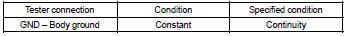
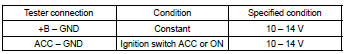
5 Inspect radio receiver assy(+b, acc, gnd)
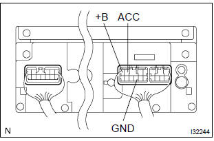
- Check that the continuity between terminals at each condition, as shown in the chart.
Standard:
- Check that the voltage between terminals at each condition, as shown in the chart.
Standard:

Repair or replace harness or connector


Other materials:
Optimal use of the multimedia system
On the “Sound Settings” screen, sound quality (Treble/Mid/ Bass), volume balance
can be adjusted.
How to adjust the sound settings and sound quality
1 2 3 Select “-” or “+” to adjust the treble, mid or bass to a level between
-5 and 5.
4 5 Select “Front” or “Rear” to adjus ...
Floor shift cable transmission control select
Replacement
Hint: components:
1. Remove air conditioner unit assy
Hint:
refer to the instructions for removal of the air conditioner unit assy.
2. Separate air bag sensor assy center
remove the 3 bolts, separate the airbag sensor assy center.
3. Remove exhaust pipe assy
4. Remo ...
Inspection
1. Fuel injector assy
Inspect injector resistance.
Using an ohmmeter,measure the resistance between
the terminals.
Resistance: 13.4 – 14.2 Ω at 20 c (68 f)
Inspect injector inspection
Caution:
keep injector clear of sparks during the test.
Purch ...