Toyota Corolla (E120) 2002–2008 Repair Manual / Diagnostics / Sfi system / Evaporative emission control
system leak detected / Circuit description
Toyota Corolla (E120): Circuit description
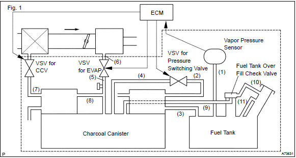
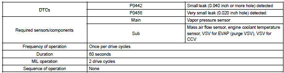
The vapor pressure sensor and the vsv for the canister closed valve (ccv) are used to detect abnormalities in the evaporative emission control system. The ecm decides whether there is an abnormality in the evaporative emission control system based on the vapor pressure sensor signal.
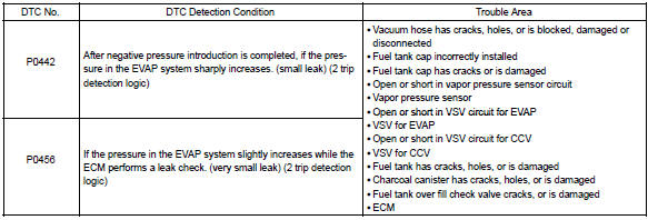
Dtc p0442 or p0456 is recorded by the ecm when evaporative emissions leak from the components within the dotted line in fig. 1 Below, or when the vapor pressure sensor malfunctions.
Hint
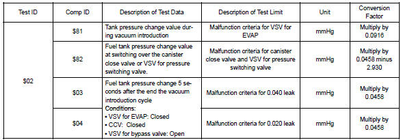
: typical dtc output of each trouble part.

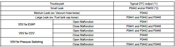
*1: Ecm may output some other dtcs combination.
*2: Refer to dtc p0441 and p0446
Monitor description
The evaporative emission system consists of the vapor pressure sensor, the canister close valve (ccv), the vsv for pressure switching valve and the vsv for evap (purge vsv), those are used to detect malfunction in the system by ecm.
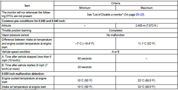
This test will run once per driving cycle when the ecm detects stable vapor pressure in the fuel tank. While the vehicle is being driven on rough or winding roads, the movement of the fuel in the tank will cause unstable fuel tank vapor pressures and the diagnostic test will not executed.
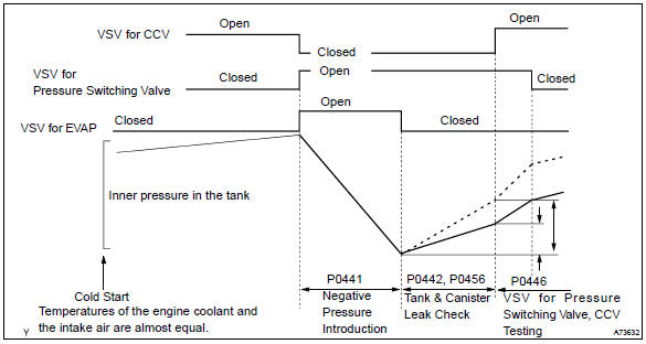
The ecm performs the following steps:
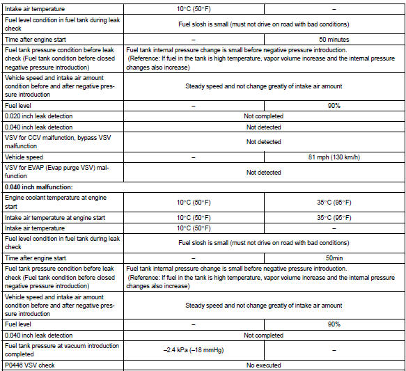
- the ccv is closed. (Shutting the system)
- the fuel tank pressure stability is checked. The diagnostic is disabled if the pressure change is more than specified value.
- the vsv for evap is opened. This introduces a negative pressure from the intake manifold to the fuel tank.
- the vsv for evap is closed and the negative pressure is sealed in the fuel tank.
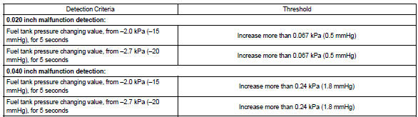
- the ecm monitors the increase in fuel tank pressure for:
- rapid increase in the internal pressure i.E. A large leak: 0.040 Or more
- pressure rise just above normal
If the ecm detects either of above conditions, it will interpret this as a leak in the evap system. The ecm will illuminate the mil (2–trip detection logic) and set a dtc.
Monitor strategy
Typical enabling conditions
Typical malfunction thresholds
Monitor result (mode 06 data)
Refer for detailed information on checking monitor status.


Other materials:
On–vehicle inspection
1. Inspect speedometer
check the operation.
Using a speedometer tester, inspect the speedometer fro allowable
indication error and check
the operation of the odometer.
Reference:
Notice:
tire wear and tire over or under inflation will increase the indication error.
...
Inspection procedure
1 Check security indicator light
Remove the security indicator.
check the indicator light, as shown in the illustration and
table.
Standard:
2 Check wire harness (tvip ecu security indicator)
Disconnect the tvip ecu and security indicator connectors.
...
Inspection procedure
1 Check door lock
2 Check wire harness (tvip ecu door lock)
Disconnect the tvip ecu and door lock connectors.
check the continuity between the terminals of the tvip
ecu and door lock connectors, as shown in the illustration
and table.
Standard:
3 Check wire harness ...