Toyota Corolla (E120) 2002–2008 Repair Manual / Diagnostics / Supplemental restraint system / Short in d squib (2nd step) circuit / Inspection procedure
Toyota Corolla (E120): Inspection procedure
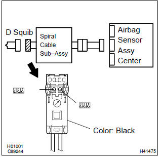
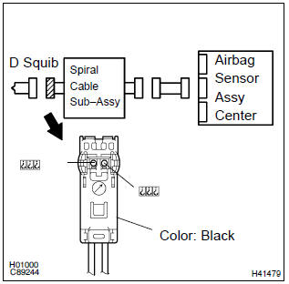
1 Check d squib circuit(airbag sensor assy center – horn button assy)
- Disconnect the negative (–) terminal cable from the battery, and wait at least for 90 seconds.
- disconnect the connectors between the airbag sensor assy center and the horn button assy.
- release the airbag activation prevention mechanism of the connector (on the airbag sensor assy center side) between the airbag sensor assy center and the spiral cable sub–assy .
- for the black connector (on the spiral cable sub–assy
side ) between the horn button assy and the spiral cable
sub–assy, measure the resistance between d2+ and
d2–.
Ok: resistance: 1 mw or higher


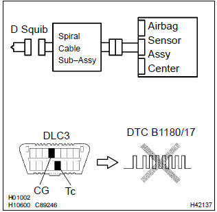
2 Check air bag sensor assy center
Sst 09843–18040
- Connect the connector to the airbag sensor assy center.
- connect the negative (–) terminal cable to the battery, and wait at least for 2 seconds.
- turn the ignition switch to on, and wait at least for 20 seconds.
- clear the dtc stored in memory .
- turn the ignition switch to lock, and wait at least for 20 seconds.
- turn the ignition switch to on, and wait at least for 20 seconds.
- check the dtc .
Ok: dtc b1180/17 is not output.
Hint
: codes other than code b1180/17 may be output at this time, but they are not relevant to this check.


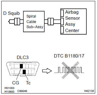
3 Check d squib
Sst 09843–18040
- Turn the ignition switch to lock.
- disconnect the negative (–) terminal cable from the battery, and wait at least for 90 seconds.
- connect the horn button assy connectors.
- connect the negative (–) terminal cable to the battery, and wait at least for 2 seconds.
- turn the ignition switch to on, and wait at least for 20 seconds.
- clear the dtc stored in memory .
- turn the ignition switch to lock, and wait at least for 20 seconds.
- turn the ignition switch to on, and wait at least for 20 seconds.
- check the dtc .
Ok: dtc b1180/17 is not output.
Hint
: codes other than code b1180/17 may be output at this time, but they are not relevant to this check.


Use simulation method to check
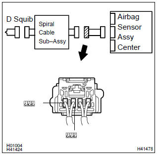
4 Check instrument panel wire(airbag sensor assy center – spiral cable sub–assy)
- Disconnect the connector of the instrument panel wire.
- release the airbag activation prevention mechanism of the connector (on the airbag sensor assy center side) between the airbag sensor assy center and the spiral cable sub–assy .
- for the connector (on the spiral cable sub–assy side) between
the airbag sensor assy center and the spiral cable
sub–assy, measure the resistance between d2+ and
d2–.
Ok: resistance: 1 mw or higher

5 Check spiral cable sub–assy
- Release the airbag activation prevention mechanism of the spiral cable sub–assy connector on the airbag sensor assy center side .
- for the black connector (on the spiral cable sub–assy
side) between the horn button assy and the spiral cable
sub–assy, measure the resistance between d2+ and
d2–.
Ok: resistance: 1 mw or higher


Use simulation method to check


Other materials:
Inspection
1. Inspect inner rear view mirror assy
Inspect the electro chromic inner mirror operation.
Connect the positive (+) lead from the battery to terminal
1 and negative (–) lead to terminal 2.
) Attach black colored tape to the forward sensor to
prevent it from sensing.
&nb ...
Engine mechanical
Service data
Torque specification
...
Location of the spare tire, jack and tools
1 Luggage floor cover
2 Wheel nut wrench
3 Jack handle
4 Jack attachment*
5 Jack
6 Spare tire
7 Tool tray
*: The jack attachment is used when raising your vehicle with a floor jack.
CAUTION
■Using the tire jack
Observe the following precautions.
Improper use of the tire jack may c ...