
Toyota Corolla (E120) 2002–2008 Repair Manual / Diagnostics / Supplemental restraint system / Short in d squib (2nd step) circuit / Circuit description
Toyota Corolla (E120): Circuit description
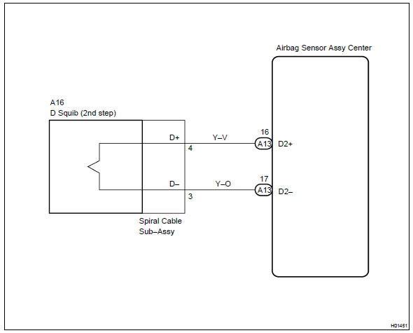
The d squib circuit consists of the airbag sensor assy center, spiral cable sub–assy and horn button assy.
It causes the srs to deploy when the srs deployment conditions are satisfied.
Dtc b1180/17 is recorded when a short is detected in the d squib circuit (2nd step).

Wiring diagram


Other materials:
Inspection procedure
Hint:
hand–held tester only:
narrowing down the trouble area is possible by performing ”a/f control” active
test (heated oxygen
sensor or other trouble areas can be distinguished).
Perform active test using hand–held tester (a/f control).
Hint:
”a/f control” is the active te ...
Rear seats
► Type A
1 Up
Pull the head restraints up.
2 Down
Push the head restraint down while pressing the lock release button.
► Type B
1 Up
Pull the head restraints up.
2 Down
Push the head restraint down while pressing the lock release button.
■Removing the head restraints ...
Screen for general settings
1 Press the “SETUP” button.
2 Select “General” on the “Setup” screen.
1 “English”, “Français” or “Español” can be selected.
2 On/off can be selected to sound beeps.
3 Select to change the screen color.
4 Select to change the keyboard layout.
5 The animatio ...