Toyota Corolla (E120) 2002–2008 Repair Manual / Diagnostics / Supplemental restraint system / Source voltage drop / Source voltage drop
Toyota Corolla (E120): Source voltage drop
The srs is equipped with a voltage–increase circuit (dc–dc converter) in the airbag sensor assy center in case the source voltage drops.
When the battery voltage drops, the voltage–increase circuit (dc–dc converter) functions to increase the voltage of the srs to normal voltage.
The diagnosis system malfunction display for this circuit is different from other circuits that is when the srs warning light remains lit up and the dtc is a normal code, source voltage drop is indicated.
Malfunction in this circuit is not recorded in the airbag sensor assy center, and the source voltage returns to normal, the srs warning light automatically goes off.

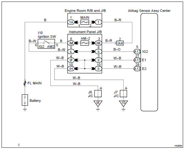
Wiring diagram


Other materials:
Installing child restraints using a seat belt
■ Rear-facing - Infant seat/convertible seat
1 Place the child restraint system on the rear seat facing the rear of the vehicle.
2 Run the seat belt through the child restraint system and insert the plate into
the buckle. Make sure that the belt is not twisted.
3 Fully extend the shou ...
Using the AUX port
This port can be used to connect a portable audio device and listen to it through
the vehicle’s speakers. Press until
“AUX” is displayed.
Connecting a portable player
■Operating portable audio devices connected to the audio system
The volume can be adjusted using the vehicle's ...
Circuit description
A flat type knock sensor (non–resonant type) has the structure that can
detect the vibration in a wider band
of frequency from about 6 khz to 15 khz and has the following features.
Knock sensors are fitted on the cylinder block to detect the engine knocking.
The sensor contains a piezoele ...