Toyota Corolla (E120) 2002–2008 Repair Manual / Diagnostics / Supplemental restraint system / Airbag sensor assy malfunction / Inspection procedure
Toyota Corolla (E120): Inspection procedure
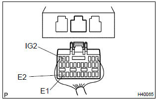
1 Check voltage at ig2 of airbag sensor assy center
- Disconnect the negative (–) terminal cable from the battery, and wait at least for 90 seconds.
- disconnect the connector of the airbag sensor assy center.
- connect the negative (–) terminal cable to the battery, and wait at least for 2 seconds.
- turn the ignition switch to on.
- measure the voltage between e1 (e2) and ig2 of the airbag
sensor assy center connector.
Ok: voltage: 10 – 14 v

2 Check air bag sensor assy center
Sst 09843–18040
- Turn the ignition switch to lock.
- disconnect the negative (–) terminal cable from the battery, and wait at least for 90 seconds.
- connect the connectors of all the srs components.
- connect the negative (–) terminal cable to the battery, and wait at least for 2 seconds.
- turn the ignition switch to on, and wait at least for 20 seconds.
- clear the dtc stored in memory .
- turn the ignition switch to lock, and wait at least for 20 seconds.
- turn the ignition switch to on, and wait at least for 20 seconds.
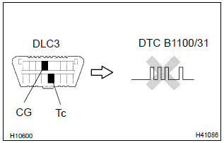
- check the dtc .
Ok: dtc b1100/31 is not output.
Hint
: codes other than code b1100/31 may be output at this time, but they are not relevant to this check.


Use simulation method to check


Other materials:
Problem symptoms table
Proceed to the reference page shown in the table below for each malfunction
symptom and troubleshoot
each circuit.
Hint:
troubleshooting of the tvip system is based on the premise that the door lock
control system and wireless
door lock control system is operating normally. Accordingly, be ...
General information
1. Basic dimensions
(a) there are two types of dimensions in the diagram.
(1) (Three-dimensional distance)
straight-line distance between the centers of two
measuring points.
(2) (Two-dimensional distance)
horizontal distance in forward/rearward direction
between the centers o ...
Evap monitor (vacuum pressure monitor)
Notice:
a cold soak must be performed prior to conducting the drive pattern to complete
the internal pressure
readiness monitor.
Cold soak preconditions
The monitor will not run unless:
mil is off.
Fuel level is approximately 1/2 to 3/4.
Altitude is 7800 feet (2400 m) or less.
...