Toyota Corolla (E120) 2002–2008 Repair Manual / Diagnostics / Audio system / No sound is heard from speaker in all modes
Toyota Corolla (E120): No sound is heard from speaker in all modes
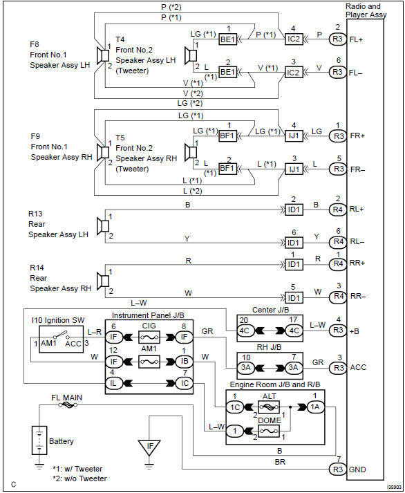
Wiring diagram
Inspection procedure
1 Check lcd (liquid crystal display) for lighting
- Lcd illumination check
- turn the ignition switch acc.
- Turn the radio receiver assembly on.
Standard: lcd illumination of the radio receiver assembly light.


2 Control fader and adjust sound balance
- Fader and balance adjustment
- operate the radio receiver assembly to adjust the fader and the balance to identify the speaker that does not sound.


3 Inspect front no.1 Speaker assy
- Preparation for check
- disconnect the connector of the speaker.
- resistance check
- check the resistance between the terminals of the speaker.
Notice
: the speaker should not be removed for checking.
Standard value: 4 Ω


4 Inspect front no.2 Speaker assy
- Check that malfunction disappear when a known good speaker is installed.
Standard: malfunction disappear.
Hint
: connect the all connectors of speakers.


5 Inspect rear speaker assy
- Preparation for check
- disconnect the connector of the speaker.
- resistance check
- check the resistance between the terminals of the speaker.
Notice
: the speaker should not be removed for checking.
Standard value: 6 w

6 Check harness and connector(between radio receiver assy and speaker)

Check and replace radio receiver assy
7 Inspect radio receiver assy(+b, acc, gnd)
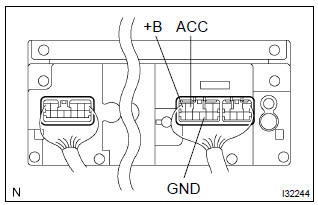
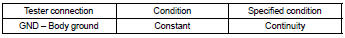
- Check that the continuity between terminals at each condition, as shown in the chart.
Standard:
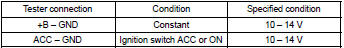
- Check that the voltage between terminals at each condition, as shown in the chart.
Standard:

Repair or replace harness or connector


Other materials:
Front wheel alignment
Adjustment
1. Inspect tire
2. Measure vehicle height
Vehicle height:
Measuring points:
a: ground clearance of front wheel center
b: ground clearance of lower suspension arm front
bolt center
c: ground clearance of axle beam set bolt center
d: ground clearance of rear wheel center
Not ...
Basic inspection
Resistance measuring condition of electronic parts
unless stated, all resistance is measured at an ambient
temperature of 20 c (68 °F). As the resistance
may be outside the specifications if measured at high temperatures
immediately after
the vehicle has been running, measu ...
Clock assy
Replacement
1. Remove console panel upper
2. Remove heater control knob
3. Remove instrument cluster finish panel
4. Remove clock assy
Using a screwdriver, disengage the 4 claws, remove the
clock as shown in the illustration.
Hint:
tape the screwdriver tip before use. ...