Toyota Corolla (E120): Pre–check
1. Srs warning light check
- Turn the ignition switch to the on position and check that the srs warning light lights up.
- check that the srs warning light goes out after approx.
6 Seconds.
Hint
: when the ignition switch is at on and the srs warning light remains on or flashes, the airbag sensor assembly has detected a malfunction code.
If, after approx. 6 Second have elapsed, the srs warning light sometimes lights up, a short in the srs warning light circuit can be considered likely. Proceed to ”srs warning light circuit malfunction”
2. Dtc check ( using diagnosis check wire)
- Present troubles codes: output the dtc.
- Turn the ignition switch to the on position and wait for approx. 60 Seconds.
- Using sst, connect terminals tc and cg of the
dlc3.
Sst 09843–18040
n
otice
: pay due attention to the terminal connecting position to avoid a malfunction.
- past troubles codes: output the dtc.
- Using service wire, connect terminals tc and cg of
the dlc3.
Sst 09843–18040
- ) turn the ignition switch to the on position and wait for approx. 60 Seconds.
Notice
: pay due attention to the terminal connecting position to avoid a malfunction.
- Read the dtc.
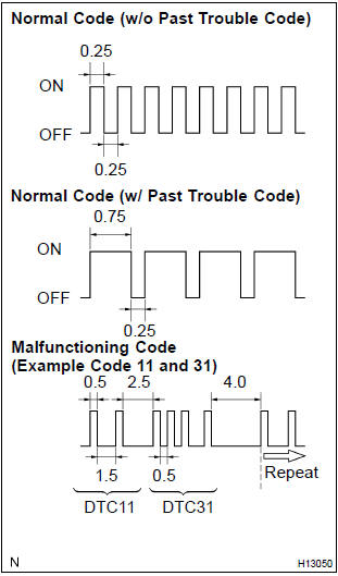
Read the 2–digit dtc as indicated by the number of times the srs warning light blinks. As an example, the blinking patterns, normal, 11 and 31 are shown in the illustration.
- Normal code indication (w/o past trouble code) the light will blink 2 times per second.
- Normal code indication (w/ past trouble code) when the past troubles code is stored in the airbag sensor assembly, the light blinks only ones a second.
- Malfunction code indication the first blinking output indicates the first digit of a 2–digit dtc. After a 1.5–Second pause, the second blinking output will indicate the second digit.
If there are 2 or more codes, there will be a 2.5–Second pause between each code. After all the codes have been output, there will be a 4.0–Second pause and they will all be repeated.
Hint: in the event of a number of trouble codes, indication will start from the smallest numbered code.
3. Dtc check (using hand–held tester)
- Hook up the hand–held tester to the dlc3.
- read the dtcs by following the prompts on the tester screen.
Hint
: please refer to the hand–held tester operator’s manual for further details.
4. Dtc clearance (not using service wire)
- When the ignition switch is turned off, the diagnostic trouble code is cleared.
Hint
: dtc might not be cleared by turning the ignition switch off. In this case, proceed to the next step.
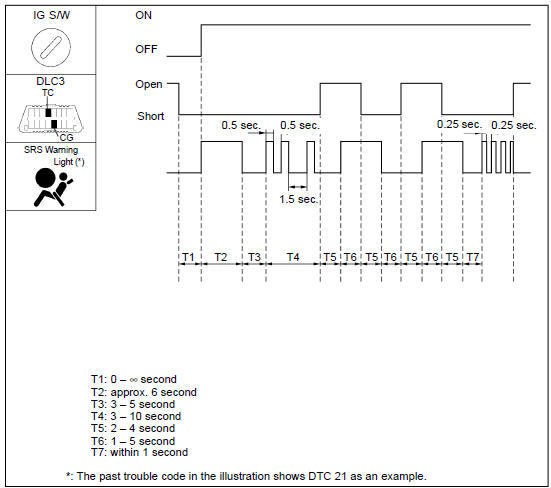
5. Dtc clearance (using service wire)
- Using a service wire, connect terminals tc and cg of the dlc3.
- disconnect terminal tc of dlc3 within 10 seconds after the dtc begins to be output, and check if the warning light lights up within 3 seconds.
- within 2.0 Seconds to 4.0 Seconds after the srs warning light lights up, connect the terminals tc and cg of the dlc3.
- light the srs warning light goes off 2.0 To 4.0 Seconds after connecting the terminals tc and cg of dlc3, then disconnect the terminal tc of the dlc3 2.0 To 4.0 Seconds after the warning light goes off.
- light the srs warning light on again 3 seconds after disconnecting terminal tc of dlc3, then within 2.0 To 4.0 Seconds after the lighting, connect terminals tc and cg of the dlc3.
- check if the srs warning light goes off 2.0 To 4.0 Seconds after connecting terminals tc and cg of dlc3, and the correct code is output 1 second after the srs warning goes off.
If dtcs are to cleared, repeat the above procedure until the codes are cleared.
6. Dtc clearance (using hand–held tester)
- Hook up the hand–held tester to the dlc3.
- clear the dtcs by following the prompts on the tester screen.
Hint
: please refer to the hand–held tester operation’s manual for further details.
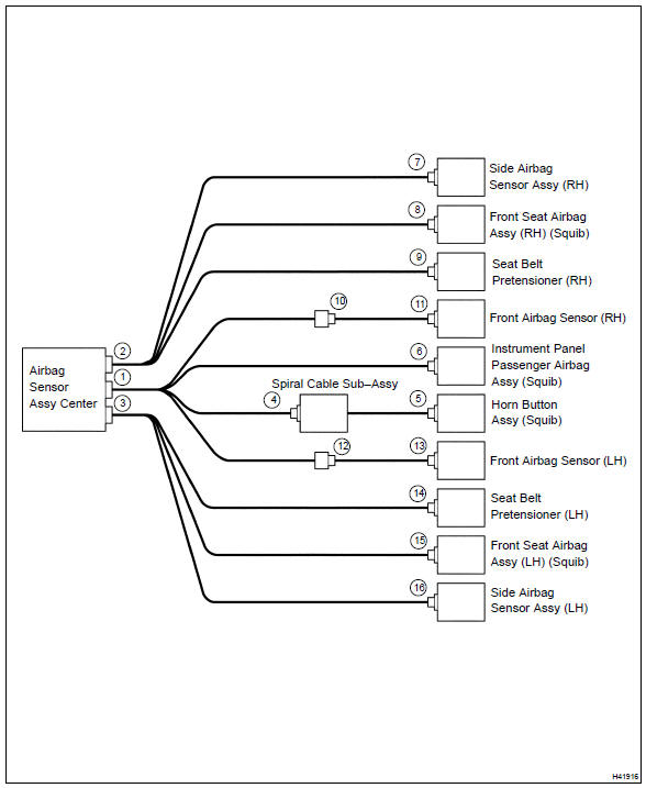
7. Release method of airbag activation prevention mechanism
- An airbag activention prevention mechanism is built into the connector
for the squib circuit of the srs.
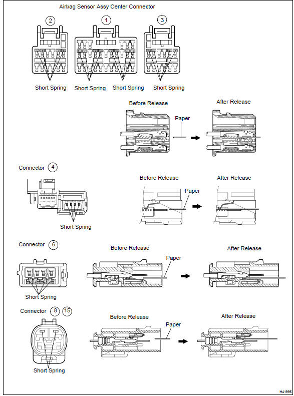
When release of the airbag activation prevention mechanism is directed in the troubleshooting procedure, as shown in the illustration of the connectors on the next pages, insert paper which has the same thickness as the male terminal between the terminal and the short spring.
Caution
: never release the airbag activation prevention mechanism on the squib connector.
Notice
:
- Do not release the airbag activation prevention mechanism unless specifically directed by the troubleshooting procedure.
- If the inserted paper is too thick the terminal and short spring may be damaged, so always use paper with the same thickness as the male terminal.


Other materials:
Replacement
Hint:
installation is in the reverse order of the removal. But the installation is
indicated only when it has a point.
1. Remove radiator grille sub–assy
Remove the 2 bolts and clip.
using a screwdriver, remove the radiator grille.
Hint:
tape the screwdriver tip before use. ...
Overhaul
1. Remove oil pump relief valve
Remove the oil pump relief valve plug, oil pump relief
valve spring and oil pump relief valve.
Oil pump relief valve plug
oil pump relief valve spring
oil pump relief valve
2. Inspect oil pump assy
Remove 3 screws and o ...
For vehicles equipped with mobile communication system
Install an antenna as far as possible away from the ecu
and sensors of the vehicle’s electronic systems.
install an antenna feeder at least 20 cm (7.87 In.) Away
from the ecu and sensors of the vehicle’s electronic systems.
For details of the ecu and sensors locations, refer ...