Toyota Corolla (E120): Overhaul
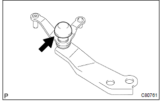
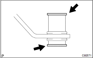
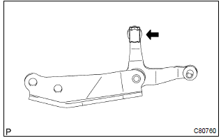
1. Remove control shift lever bush

- Remove the control shift lever bush from the selecting bellcrank assy.
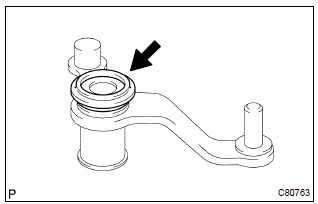
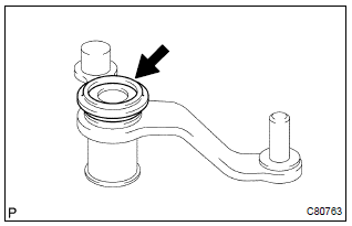
2. Remove selecting bellcrank dust cover no.1
- Remove the selecting bellcrank dust cover no.1 From the selecting bellcrank assy.
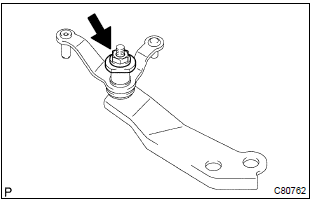
3. Remove selecting bell crank no.2

- Remove the nut, spring washer and selecting bellcrank no.2 Plate washer.
- remove the selecting bellcrank no.2 From the selecting bellcrank support.
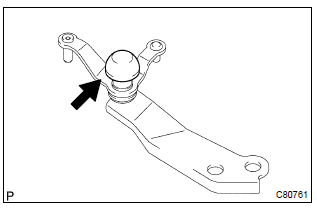
4. Remove selecting bellcrank dust cover no.2
- Remove the selecting bellcrank dust cover no.2 From the selecting bellcrank no.2.
5. Remove selecting bellcrank no.2 Bush
- Remove the 2 selecting bellcrank no.2 Bushes from the selecting bellcrank no.2.
6. Remove select spring seat no.2
- Using a screwdriver, remove the e–ring, select spring seat no.2 And select return spring no.2 From the shift & select lever shaft.
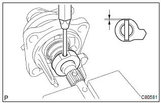
7. Remove shift lever inner no.2
- Using a pin punch (f 5 mm) and a hammer, remove the slotted pin and shift lever inner no.2 From the shift & select lever shaft.
Hint
: make sure the orientation of the shift lever inner no.2.
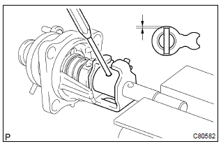
8. Remove shift lever inner no.1
- Using a pin punch (f 5 mm) and a hammer, remove the slotted pin, shift lever inner no.1 And shift inter lock plate from the shift & select lever shaft.
Hint
: make sure the orientation of the shift lever inner no.1.
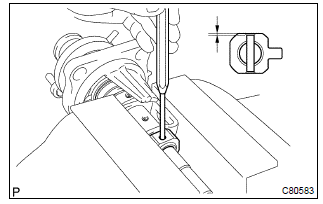
9. Remove select inner lever
- Using a pin punch (f 5 mm) and a hammer, remove the slotted pin, select inner lever, select return spring no.1 And select return spring seat no.1.
Hint
: make sure the orientation of the select inner lever.
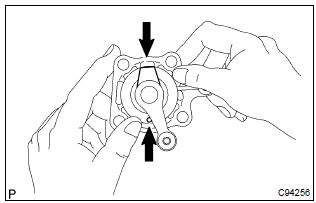
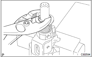
10. Remove control shaft cover
- Using 2 screwdrivers and a hammer, tap out the snap ring.
- remove the control shaft cover and shift & select lever shaft dust boot.
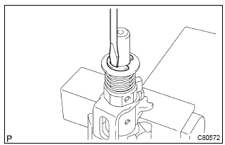
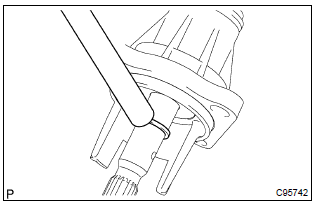
11. Remove control shaft cover oil seal
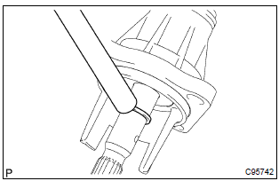
- Using a screwdriver, remove the control shaft cover oil seal from the control shaft cover.
12. Install control shaft cover oil seal
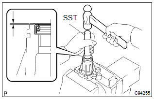
- Using sst and a hammer, install a new control shaft cover
oil seal to the control shaft cover.
Sst 09950–60010 (09951–00220), 09950–70010 (09951–07100)
drive in depth: 0.7 0.5 Mm (0.0276 0.0197 In.) - coat the lip of control shaft cover oil seal with mp grease.
13. Install control shaft cover
- Coat the shift & select lever shaft boot with mp grease, install it to the control shaft cover.
- install the control shaft cover to the shift & select lever.
Hint
: install the dust boot with the projection up and the hole side down.
- coat the shift & select lever shaft with mp grease.
- Using a brass bar and a hammer, tap in the snap ring to the shift & select lever shaft.
14. Install select inner lever
- Coat the select spring seat no.1 With mp grease, install it to the shift & select lever shaft.
- install the select return spring and select inner lever to the shift & select lever shaft.
- using a pin punch (f 5 mm) and a hammer, install the
slotted pin to the select lever inner lever.
Drive in depth: 3.0 – 4.0 Mm (0.1181 – 0.1575 In.)
15. Install shift lever inner no.1
- Coat the shift interlock plate and shift lever inner no.1 With mp grease.
- install the shift interlock plate with shift lever inner no.1 To the shift & select lever shaft.
- using a pin punch (f 5 mm) and a hammer, install the
slotted pin to the shift lever inner no.1.
Drive in depth: 0 0.5 Mm (0 0.0197 In.)
16. Install shift lever inner no.2
- Install the shift lever inner no.2 To the shift & select lever shaft.
- using a pin punch (f 5 mm) and a hammer, install the
slotted pin to the shift lever inner no.2.
Drive in depth: 0 0.5 Mm (0 0.0197 In.)
17. Install select spring seat no.2
- Coat the select spring seat no.2 With mp grease, install it with select return spring to the shift & select lever shaft.
- using a plier, install the e–ring to the shift & select lever shaft.
18. Install selecting bellcrank no.2 Bush
- Coat the selecting bellcrank no.2 Bushes with mp grease, install them to the selecting bellcrank.
19. Install selecting bellcrank dust cover no.2
- Coat the selecting bellcrank dust cover no.2 With mp grease, install it to the selecting bellcrank no.2.
20. Install selecting bell crank no.2
- Install the selecting bellcrank no.2, Selecting bellcrank
no.2 Plate washer and spring washer with nut.
Torque: 11.8 Nvm (120 Kgf·cm, 9 ft·lbf)
21. Install selecting bellcrank dust cover no.1
- Install the selecting bellcrank dust cover no.1 To the selecting bellcrank assy.
22. Install control shift lever bush
- Coat the control shift lever bush with mp grease, install it to the selecting bellcrank assy.


Other materials:
Inspection procedure
1 Check front airbag sensor (lh) circuit (to b+)(airbag sensor assy
center – airbag sensor front lh)
Disconnect the negative (–) terminal cable from the battery,
and wait at least for 90 seconds.
disconnect the connectors between the airbag sensor
assy center and the airbag ...
Customer problem analysis
Hint:
in troubleshooting, the problem symptoms must be confirmed
accurately, meaning that all preconceptions
must be set aside in order to make an accurate judgement. To ascertain what
the problem symptoms
are, it is extremely important to ask the customer about the problem and
cond ...
Child restraint systems
Before installing a child
restraint system in the vehicle,
there are precautions
that need to be observed,
different types of child
restraint systems, as well as
installation methods, etc.,
written in this manual.
Use a child restraint system
when riding with a small child
that cannot properly use a ...