Toyota Corolla (E120): Circuit description
If the engine coolant temperature (ect) does not reach 75°c (167°f) despite sufficient warm – up time has elapsed.
|
Dtc no |
Dtc detection condition |
Trouble area |
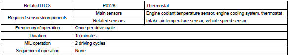
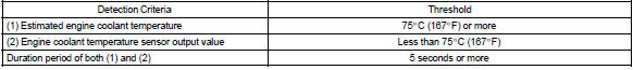
| P0128 | Condition (a), (b) and (c):
|
|
Monitor description
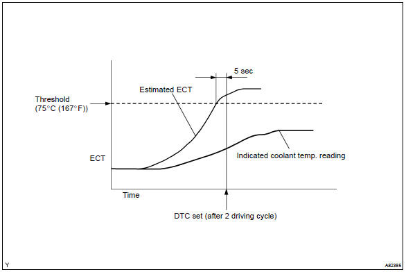
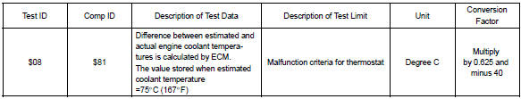
The ecm estimates the engine coolant temperature (ect) based on starting temperature, engine loads, and engine speeds. The ecm then compares the estimated ect with the actual ect. When the estimated ect reaches 75 c (167 f) the ecm checks the actual ect. If the actual ect is less than 75 c (167 f), the ecm will interpret this as a fault in the thermostat or engine cooling system or thermostat and set a dtc.
Monitor strategy
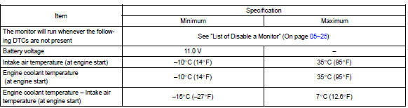
Typical enabling conditions
Typical malfunction thresholds
Component operating range

Monitor result (mode 06 data)
Refer to page 05–27 for the detailed information on checking monitor status.


Other materials:
Inspection procedure
Hint:
if different dtcs related to different systems that have terminal e2
as the ground terminal are output
simultaneously, terminal e2 may be open.
Read freeze frame data using the hand-held tester or the obd ii scan
tool. Freeze frame data records
the engine conditions when a malf ...
Overhaul
Hint:
overhaul the rh side by the same procedures with lh side.
1. Remove rear wheel
2. Drain brake fluid
Notice:
wash the brake fluid off immediately if it comes into contact with any painted
surface.
3. Remove rear brake drum sub–assy
Release the parking brake lever, and remove t ...
On–vehicle inspection
1. Inspect turn signal flasher relay circuit
Disconnect the connector from the turn signal flasher
relay and inspect the connector on wire harness side as
shown in the chart.
Standard:
Connect the connector to the turn signal flasher and inspect
the wire harness side connector ...