Toyota Corolla (E120): On–vehicle inspection
1. Check fuel pump operation
- Connect the hand–held tester to the dlc3.
- turn the ignition switch on and hand–held tester main
switch on.
Notice
: do not start the engine.
- select the active test mode on the hand–held tester.
- please refer to the hand–held tester operator’s manual for further details.
- if you have no hand–held tester, connect the positive (+) lead form the battery to terminal 4 of the connecter, and the negative (–) lead to terminal 5.
Notice
:
- these tests must be done quickly (within 10 seconds) to prevent the coil burning out.
- Keep the fuel pump as far away from the battery as possible.
- Always do the switching at the battery side.
2. Check fuel pressure
- Prepare for inspection.
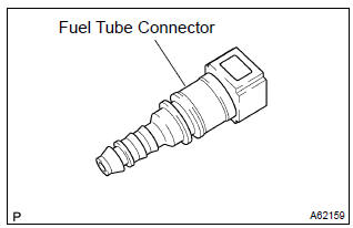
- Purchase a new fuel tube, and take out the fuel tube connector from its tube.
Hint
: part no. 23901–0D010
- work for prevent gasoline from spilling out.
- disconnect the efi fuel pipe clamp.
- disconnect the fuel tube from the fuel main tube.
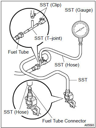
- Install sst (pressure gauge) as shown in the illustration
by using the sst and fuel tube connector.
Sst 09268–41047 (90467–13001, 95336–08070), 09268–45014 (09268–41200, 09268–41220, 09268–41250, 90467–13001)
- wipe off any splattered gasoline.
- ) start the engine.
- measure the fuel pressure at idle.
Fuel pressure: 304 – 343 kpa (3.1 – 3.5 Kgfvcm2, 44 – 50 psi)
- stop the engine.
- check that the fuel pressure remains as specified for 5
minutes after the engine has stopped.
Fuel pressure:
147 kpa (1.5 Kgfvcm2, 21 psi) or more
If pressure is not as specified, check the fuel pump, pressure regulator and/or injectors.
- after checking fuel pressure, disconnect the negative (–) terminal cable from the battery and carefully, remove the sst and fuel tube connector to prevent gasoline from the splashing.
- reconnect the fuel tube to fuel main tube.
- install the efi fuel pipe clamp.
- check fuel leak.


Other materials:
Outer rear view mirror assy lh
Replacement
Hint:
installation is according to the reverse order of the removal.
In the rh side, work in the same procedure as in the lh side.
1. Remove front armrest assy lh
2. Remove power window regulator master switch assy (w/ power window)
3. Remove front armrest base panel upper ...
Inspection procedure
Hint:
when the throttle position is slightly opened (the accelerator pedal
is slightly depressed) because a
floor carpet is overlapped on the accelerator pedal, or if not fully
releasing the accelerator pedal, etc.,
Dtc p505 will possibly be detected.
Read freeze frame data using the ...
Inspection procedure
Hint:
the switch described in this text is a switch for transmitting signals which is
built in the door control transmitter.
1 Check wireless door lock control functions
Normal
2 Replace transmitter battery with normal one
After replacing the transmitter battery with a new or normal o ...