Toyota Corolla (E120): Inspection
1. Fuel injector assy
- Inspect injector resistance.
- Using an ohmmeter,measure the resistance between
the terminals.
Resistance: 13.4 – 14.2 Ω at 20 c (68 f)
- Inspect injector inspection
Caution
: keep injector clear of sparks during the test.
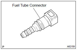
- Purchase a new fuel tube, and take out the fuel tube connector from its tube.
Hint
: part no. 23901–0D010
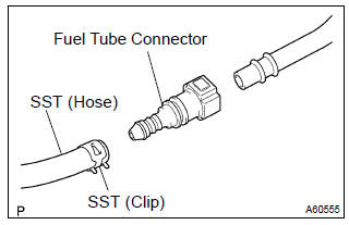
- Connect sst and fuel tube connector to the fuel
pipe.
Sst 09268–41047 (90467–13001, 95336–08070)
Caution
: perform connecting operations of the fuel tube connector (quick type) after observing the precautions.
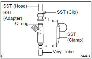
- Install an o–ring to the fuel injector.
- Connect sst (union and hose) to fuel the injector, and hold the fuel injector to prevent gasoline from splashing out. sst 09268–41047 (90467–13001, 95336–08070, 09268–41110, 09268–41300)
- Put the fuel injector into a graduated cylinder.
Hint
: install a suitable vinyl tube onto the injector to prevent gasoline from splashing out.
- Operate the fuel pump.
- Connect sst to the connector of fuel injector.
Sst 09842–30080
- connect sst to the battery for 15 seconds, and
measure the injection volume with a graduated cylinder.
Test the each fuel injector 2 or 3 time.
Injection volume: 60 – 73 cm3 (3.7 – 4.5 Cu in.) Per 15 seconds difference between each injector: 13 cm3 (0.8 Cu in.) Or less
- Inspect leakage
- in the condition above, disconnect the test probes
of the from the battery, and check the fuel leakage
from the fuel injector.
Fuel drop: 1 drop or less per 12 minutes
2. Fuel pump
- Inspect fuel pump resistance.
- Using an ohmmeter, measure the resistance between
the terminals.
Resistance: 0.2 – 3.0 W at 20 c (68 f)
- inspect fuel pump operation
- apply battery voltage to both terminals. Check that the pump operates.
Notice
:
- these tests must be done quickly (within 10 seconds) to prevent the coil from burning out.
- Keep fuel pump as far away from the battery as possible.
- Always do the switching at the battery side.


Other materials:
Repair
1. Steering off center repair procedure
Inspect steering wheel off center.
Apply masking tape on the top center of the steering
wheel and steering column upper cover.
Driving the vehicle on a straight line for 100 meters
at a constant speed of 35 mph (56 km/h), and ho ...
SRS airbags
The SRS airbags inflate when the vehicle is subjected to certain
types of severe impacts that may cause significant injury
to the occupants. They work together with the seat belts to
help reduce the risk of death or serious injury.
SRS airbag system
■ Location of the SRS airbags
SRS front airbags ...
Using the key (vehicles
without a smart key system
and with a wireless
remote control function)
Releasing
To release the key, press the button
Folding
To stow the key, press the button
then fold the key.
Using the mechanical key
(vehicles with a smart key
system)
To take out the mechanical key,
slide the release button and take
the key out.
The mechanical key can only be
inserted in o ...