Toyota Corolla (E120) 2002–2008 Repair Manual / Diagnostics / Sfi system / Camshaft position ”a” actuator
circuit / Inspection procedure
Toyota Corolla (E120): Inspection procedure
Hint
: read freeze frame data using the hand–held tester or the obd ii scan tool. Freeze frame data records the engine conditions when a malfunction is detected. When troubleshooting, it is useful for determining whether the vehicle was running or stopped, the engine was warmed up or not, the air–fuel ratio was lean or rich, etc. At the time of the malfunction.
Hand–held tester
1 Perform active test by hand–held tester(operate ocv)
- Connect the hand–held tester to the dlc3.
- start the engine and warm it up.
- turn the ignition switch on and push the hand–held tester main switch on.
- select the item ”diagnosis / enhanced obd ii / active test / vvt ctrl b1”.
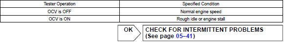
- check the engine speed when operating the oil control valve (ocv) by the hand–held tester.
Standard:

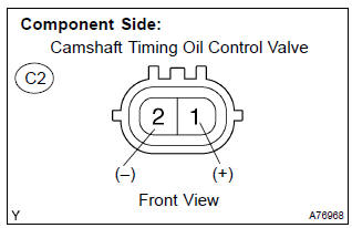
2 Inspect camshaft timing oil control valve assy(ocv)

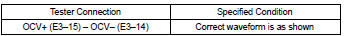
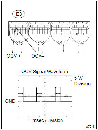
3 Inspect ecm(ocv signal)
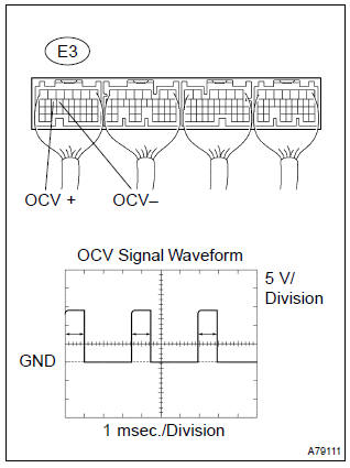
- Inspection using the oscilloscope.
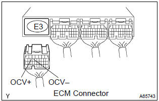
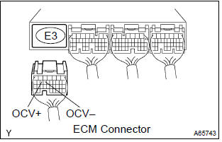
- during idling, check the waveform between the terminals of the e3 ecm connector.
Standard:


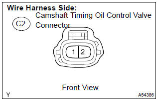
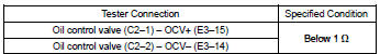
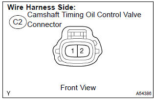
4 Check harness and connector(camshaft timing oil control valve (ocv) – ecm)
- Disconnect the c2 camshaft timing oil control valve connector.
- disconnect the e3 ecm connector.
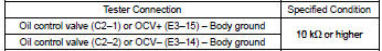
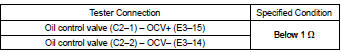
- check the resistance between the wire harness side connectors.
Standard (check for open):
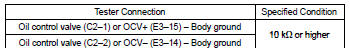
Standard (check for short):
- Reconnect the camshaft timing oil control valve connector.
- reconnect the ecm connector.

Check for intermittent problems
Obdii scan tool (excluding hand–held tester):
1 Inspect camshaft timing oil control valve assy(operate ocv)
- Disconnect the c2 camshaft timing oil control valve connector.
- apply positive battery voltage between the terminals of the camshaft timing oil control valve.
- check the engine speed.
Standard
: engine speed is rough idle or engine is stalled.
- reconnect the camshaft timing oil control valve connector.

2 Inspect ecm(ocv signal)
- Inspection using the oscilloscope.
- during idling, check the waveform between the terminals of the e3 ecm connector.
Standard:


3 Check harness and connector(camshaft timing oil control valve (ocv) – ecm)
- Disconnect the c2 camshaft timing oil control valve connector.
- disconnect the e3 ecm connector.
- check the resistance between the wire harness side connectors.
Standard (check for open):
Standard (check for short):
- Reconnect the camshaft timing oil control valve connector.
- reconnect the ecm connector.

Check for intermittent problems


Other materials:
Locking the doors from the outside without a key
1 Move the inside lock button to the lock position.
2 Close the door.
► Vehicles without a smart key system
The door cannot be locked if either of the front doors is open and the key is in
the engine switch.
► Vehicles with a smart key system
The door cannot be locked if the engin ...
Circuit inspection
1 Check d squib circuit(airbag sensor assy center – horn button
assy)
Disconnect the negative (–) terminal cable from the battery,
and wait at least for 90 seconds.
disconnect the connectors between the airbag sensor
assy center and the horn button assy.
connect the ...
Switching the display
Press to display or hide the album
title.
If there is additional text, is
displayed.
Press and hold to display the remaining
text.
■USB memory functions
●Depending on the USB memory that is connected to the system, the device itself
may not be operable and certain function ...