Toyota Corolla (E120) 2002–2008 Repair Manual / Diagnostics / Sfi system / Camshaft position ”a” actuator
circuit / Circuit description
Toyota Corolla (E120): Circuit description
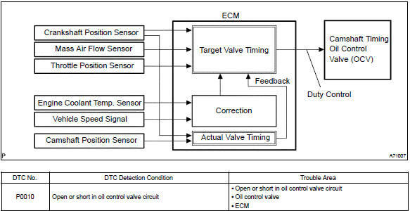
The variable valve timing (vvt) system includes the ecm, the oil control valve (ocv) and the vvt controller.
The ecm sends a target ”duty–cycle” control signal to the ocv. This control signal, applied to the ocv, regulates the oil pressure supplied to the vvt controller. Camshaft timing control is performed based on engine operation conditions such as the intake air volume, throttle position and engine coolant temperature.
The ecm controls the ocv, based on the signals output from the sensors. The vvt controller regulates the intake camshaft angle using oil pressure through the ocv. As result, the relative position between the camshaft and the crankshaft is optimized, and the engine torque improves, fuel economy improves, and exhaust emissions decrease under overall driving conditions. Also, the ecm detects the actual valve timing using signals from the camshaft position sensor and the crankshaft position sensor, and performs the feedback control. This is how target valve timing is verified by the ecm.
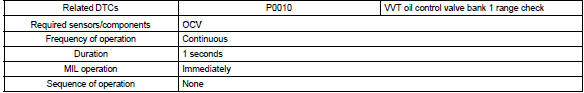
Monitor description
After the ecm sends the ”target” duty–cycle signal to the ocv, the ecm monitors the ocv current to establish an ”actual” duty–cycle. The ecm detects a malfunction and sets a dtc when the actual duty–cycle ratio varies from the target duty–cycle ratio.
Monitor strategy
Typical enabling conditions
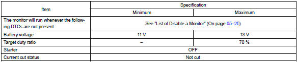
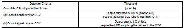
Typical malfunction thresholds
Component operating ra

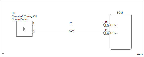
Wiring diagram


Other materials:
Aluminum wheel precautions (if equipped)
● Use only Toyota wheel nuts and wrenches designed for use with your aluminum
wheels.
● When rotating, repairing or changing your tires, check that the wheel nuts are
still tight after driving 1000 miles (1600 km).
● Be careful not to damage the aluminum wheels when using tir ...
Confirmation driving pattern
Connect the hand–held tester or the obd ii scan tool to the dlc3.
record dtcs and the freeze frame data.
set the check mode using the hand–held tester .
read the value on the misfire counter for each cylinder when
idling. If the value is displayed on the
misfire c ...
Inspection procedure
1 Check seat position air bag sensor
Sst 09843–18040
Turn the ignition switch to on, and wait at least for 20 seconds.
clear the dtc stored in memory .
turn the ignition switch to lock, and wait at least for 20
seconds.
turn the ignition switch to on, and wait at ...