Toyota Corolla (E120): Inspection
1. Cooler thermistor no.1
- Check resistance between terminals 1 and 2 of cooler
thermistor no. 1 At each temperature, as shown in the
chart.
Resistance:
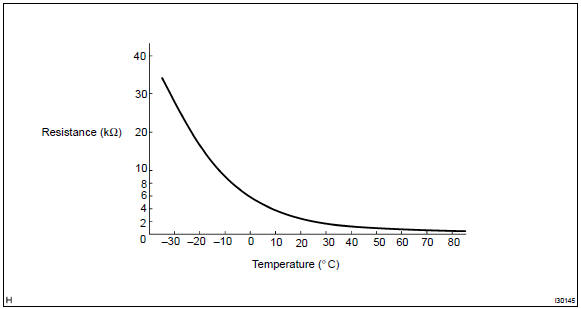
If resistance value is not as specified, replace the sensor.
2. Cooler and accessory assy
- Inspect blower switch continuity.
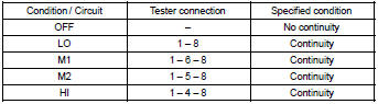
If continuity is not as specified, replace the air conditioner control assy.
- inspect illumination operation.
Connect the positive (+) lead from the battery to terminal 2 and negative (–) lead to terminal 3 then check that the illuminations light up.
If there is bulb not light up, replace the bulb.
3. Cooler switch hole cover
- Inspect switch continuity.
Check the continuity between terminals while switch is pressed, as shown in the chart.

If continuity is not as specified, replace the cooler switch.
- inspect illumination operation.
Connect the positive (+) lead from the battery to terminal 4 and negative (–) lead to terminal 3 then check that the illuminations light up.
If operation is not as specified, replace the cooler switch.
- inspect indicator operation.
- Connect the positive (+) lead from the battery to terminal 2 and the negative (–) lead to terminal 1.
- Push the a/c button in and then check that the indicator lights up.
If operation is not as specified, replace the cooler switch.
- inspect dimming operation
- connect the positive (+) lead from the battery to terminal 2 and the negative (–) lead to terminal 1 while press the switch.
- Connect the positive (+) lead from battery to terminal 4 and then check that the indicator dims.
If operation is not as specified, replace the cooler switch.
4. Blower resistor
- Measure resistance between terminals, as shown in the chart below.
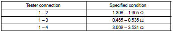
If resistance is not as specified, replace the blower resistor.
5. Blower w/fan motor sub–assy
- Connect the positive (+) lead from the battery to terminal 2 and negative (–) to terminal 1, then check that the motor operation smoothly.
If operation is not as specified, replace the blower motor.
6. Heater blower motor relay assy
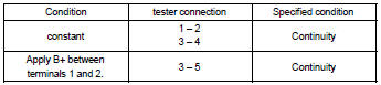
If continuity is not as specified, replace the heater blower motor relay.
7. Magnet–clutch relay

If continuity is not as specified, replace the magnet–clutch relay.


Other materials:
Inspection procedure
1 Check p squib circuit(airbag sensor assy center – instrument
panel passenger airbag assy)
Disconnect the negative (–) terminal cable from the battery,
and wait at least for 90 seconds.
disconnect the connectors between the airbag sensor
assy center and the instrument panel ...
Problem symptoms table
Proceed to the reference page shown in the table below for each malfunction
symptom and troubleshoot
each circuit.
Hint:
troubleshooting of the tvip system is based on the premise that the door lock
control system and wireless
door lock control system is operating normally. Accordingly, be ...
Steering column
Preparation
Sst
Recomended tools
Equipment
...