
Toyota Corolla (E120) 2002–2008 Repair Manual / Diagnostics / Cruise control system / Stop light switch circuit / Inspection procedure
Toyota Corolla (E120): Inspection procedure
1 Check operation(stop lamp swtich assy)
- Check that the stop light comes on when the brake pedal is depressed, and turns off when the brake pedal is released.


2 Input signal check
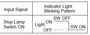
- See input signal check on page 05–745.
- check the indicator light when the brake pedal is depressed.
Ok: the indicator light goes off when the brake pedal is depressed.


3 Inspect terminal voltage(stp–)
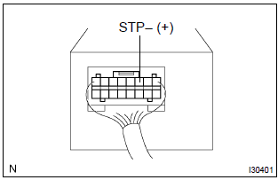
- Remove the cruise control ecu assy with connectors still connected.
- turn the ignition switch to on.
- measure voltage between terminal 3 (stp–) of cruise
control ecu assy connector and body ground, when the
brake pedal is depressed and released.
Ok:



4 Check harness and connector(between cruise control ecu assy and stop lamp switch assy)
- Check for open and short circuit in harness and connector between cruise control ecu assy and stop lamp switch assy


Check and replace cruise control ecu assy


Other materials:
Fastening and releasing
the seat belt
To fasten the seat belt, push
the plate into the buckle until
a click sound is heard.
To release the seat belt,
press the release button A.
■Emergency locking retractor
(ELR)
The retractor will lock the belt during
a sudden stop or on impact. It may
also lock if you lean forward too
quickl ...
Engine (ignition) switch (vehicles
without a smart key system)
Starting the engine
1. Check that the parking brake
is set.
2. Check that the shift lever is in
P.
3. Firmly depress the brake
pedal.
4. Turn the engine switch to
START to start the engine.
■If the engine does not start
The engine immobilizer system may
not have been deactivated.
Contact your Toy ...
Replacement
Hint:
installation is in the reverse order of the removal. But the installation is
indicated only when it has a point.
1. Remove luggage compartment door cover
2. Remove rear spoiler
remove the 2 screws.
disconnect the wire harness connector.
put protective tape.
&nb ...