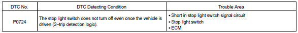
Toyota Corolla (E120): Circuit description
The purpose of this circuit is to prevent the engine from stalling while driving in lock–up condition, when brakes are suddenly applied.
When the brake pedal is depressed, this switch sends a signals to the ecm. Then the ecm cancels the operation of the lock–up clutch while braking is in progress.
Monitor description
The circuit prevents the engine from stopping when the vehicle is stopped by sudden braking when the torque converter clutch is in the ”lock–up” mode. The ecm receives the signal from the stop light switch at the time brake pedal is depressed. Then, the ecm sends the signal to the lock–up solenoid valve not to be in lock–up condition. When the stop light switch remains on during ”stop and go” driving, the ecm interprets this as a fault in the stop light switch and the mil comes on. The vehicle must stop and go (3 km/h (2 mph) to 30 km/h (19 mph)) ten times for two driving cycles in order to detect malfunction.
Monitor strategy
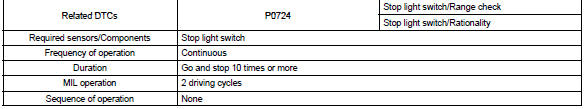
Typical enabling condition
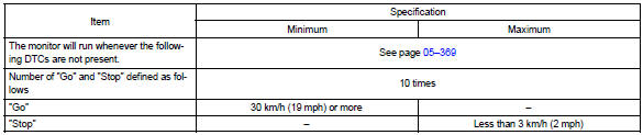
Typical malfunction thresholds

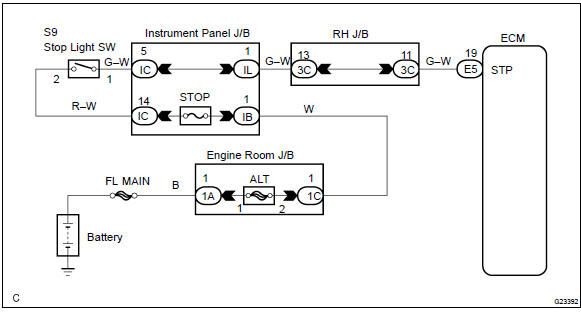
Wiring diagram


Other materials:
Front passenger occupant classification system
Your vehicle is equipped with a front passenger occupant classification system.
This system detects the conditions of the front passenger seat and activates or
deactivates the devices for the front passenger.
1 SRS warning light
2 Seat belt reminder light
3 “AIR BAG OFF” indicator light ...
Overhaul
1. Remove generator pulley
Sst 09820–63010 (09820–06010, 09820–06020)
Hint:
Hold sst 1 – a with a torque wrench, and tighten sst 1
– b clockwise to the specified torque.
Torque: 39 nvm (398 Kgf·cm, 29 ft·lbf)
Notice:
check that sst is secured to the rotor shaft.
...
Bluetooth® audio/phone
The following can be performed using Bluetooth® wireless communication:
■ Bluetooth® audio
The Bluetooth® audio system enables you to enjoy music played on a portable
player from the vehicle speakers via wireless communication.
This audio system supports Bluetooth®, a wireless data sy ...