Toyota Corolla (E120): Replacement
1. Remove engine under cover rh
2. Drain coolant
3. Remove front wheel rh
4. Remove cylinder head cover no.2
- Remove the 2 nuts, 2 clips and cylinder head cover.
5. Remove fan and generator v belt
- Turn the v–ribbed belt tensioner slowly clockwise and loosen it. Then, remove the fan and generator v belt and put back the v–ribbed belt tensioner little by little and fix it quietly.
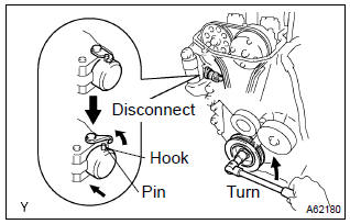
6. Separate vane pump assy
Ntice:
do not disconnect the hose.
7. Remove generator assy
8. Remove engine mounting insulator sub–assy rh
- Remove the ps oil pump reservoir and put it aside.
- place a wooden block between the jack and engine, and set the jack, then remove the 4 bolts, the 2 nuts and engine mounting insulator rh.
9. Disconnect engine wire
- Remove the 5 clamps from the 5 clamp brackets.
- disconnect the 4 ignition coil connectors.
- Remove the bolt and nut installing the engine wire.
10. Remove ignition coil assy
- Remove the 4 bolts and 4 ignition coils.
11. Disconnect ventilation hose
- Disconnect the ventilation hose from the cylinder head cover.
12. Disconnect ventilation hose no.2
- Disconnect the ventilation hose from the cylinder head cover.
13. Remove cylinder head cover sub–assy
- Remove the 9 bolts, 2 seal washers, 2 nuts, 3 clamp brackets and cylinder head cover.
14. Set no. 1 Cylinder to tdc/compression
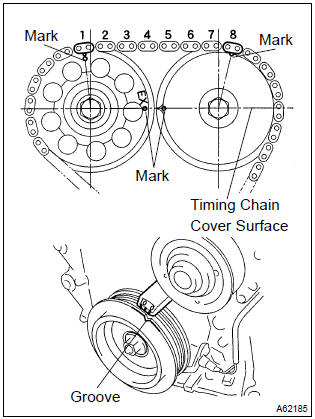
- Turn the crankshaft pulley, and align its groove with timing mark ”0” of the timing chain cover.
- check that the point marks of the camshaft timing sprocket and vvt timing sprocket are in straight line on the timing chain cover surface as shown in the illustration.
Hint
: if not, turn the crankshaft 1 revolution (360 ) and align the marks as above.
15. Remove crankshaft pulley
- Using sst, remove the pulley bolt.
Sst 09960–10010 (09962–01000, 09963–01000)
- remove the crankshaft pulley from the crankshaft.
16. Remove v–ribbed belt tensioner assy
- Remove the bolt, nut and v–ribbed belt tensioner.
Hint
: handle a jack up and down to remove the bolt.
17. Remove water pump assy
18. Remove transverse engine engine mounting bracket

- Remove the 3 bolts and transverse engine engine mounting bracket
19. Remove crank position sensor
- Remove the 2 bolts installing the crank position sensor.
20. Remove chain tensioner assy no.1
- Remove the 2 nuts and chain tensioner.
Notice
: be sure not to revolve the crankshaft without the chain tensioner.
21. Remove timing chain or belt cover sub–assy
- Remove the 11 bolts and nuts.
- using a torx wrench socket (e8), remove the stud bolt.
- remove the timing chain cover by prying the portions between the cylinder head and cylinder block with a screwdriver.
Notice
: be careful no tot damage the contact surfaces of the timing chain cover, cylinder head and cylinder block.
22. Remove timing gear cover oil seal
- Using a screwdriver, remove the oil seal.
23. Remove crankshaft position sensor plate no.1
24. Remove chain tensioner slipper
- remove the bolt and chain tensioner slipper.
25. Remove chain sub–assy
- Remove the timing chain with the crankshaft timing gear plying screwdrivers as shown in the illustration.
Notice
:
- put shop rag to protect the engine.
- In case of revolving the camshafts with the chain off the sprockets, turn the crankshaft 1/4 revolution for valves not to touch the pistons.
26. Install chain sub–assy
- Set no. 1 Cylinder to tdc/compression.
- Turn the hexagonal wrench head portion of the camshafts, and align the point marks of the camshaft timing sprockets.
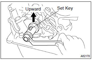
- Using a crankshaft pulley bolt, turn the crankshaft and set the set key on the crankshaft upward.
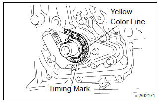
- Install the timing chain on the crankshaft timing sprocket with the yellow color link aligned with the timing mark on the crankshaft timing sprocket.
Hint
: three yellow color links are on the chain.
- Using sst, install the crankshaft timing sprocket.
Sst 09223–22010
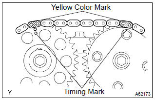
- Install the timing chain on the camshaft timing sprockets with the yellow color links aligned with the timing marks on the camshaft timing sprockets.
27. Install chain tensioner slipper
- install the chain tensioner slipper with the bolt.
Torque: 19 nvm (194 Kgf·cm, 14 ft·lbf)
28. Install crankshaft position sensor plate no.1
- Install the plate with the ”f” mark facing forward.
29. Install timing gear cover oil seal
- Apply mp grease to a new oil seal lip.
- using sst, tap in the oil seal until its surface is flush with
the timing chain cover edge.
Sst 09223–22010
N
otice
: keep the lip off foreign materials.
30. Install timing chain or belt cover sub–assy
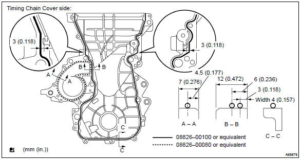
- Remove any old packing material from the contact surface.
- apply seal packing in the shape of bead (diameter 3.5
Mm – 4.5 Mm (0.1379 – 0.177 In.)) Consequently as
shown in the illustration.
Seal packing: water pump part part no. 08826–00100 Or equivalent other part part no. 08826–00080 Or equivalent.
Notice
:
- remove any oil from the contact surface.
- Install the oil pan within 3 minutes after applying seal packing.
- Do not put into engine oil within 2 hours after installing.
- Install the timing chain cover with the 11 bolts and nut.
Torque:
a: 13 nvm (133 Kgf·cm, 10 ft·lbf) b: 19 nvm (194 Kgf·cm, 14 ft·lbf) - using a torx wrench socket (e8), install the stud bolt.
Torque: 9.5 Nvm (97 Kgf·cm, 84 in.Vlbf)
31. Install chain tensioner assy no.1
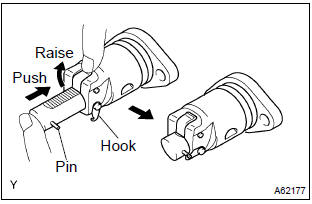
- Check the o–ring is clean, and set the hook as shown in the illustration.

- Apply engine oil to the chain tensioner and install it withe
2 nuts.
Torque: 9.0 Nvm (92 Kgf·cm, 80 in.Vlbf)
N
otice
: when installing the tensioner, set the hook again if the hook release the plunger.
32. Install crank position sensor
- Install the crank position sensor with the 2 bolts.
Torque: 9.0 Nvm (92 Kgf·cm, 80 in.Vlbf)
33. Install transverse engine engine mounting bracket
- Install the transverse engine engine mounting bracket
with the 3 bolts.
Torque: 47 nvm (479 Kgf·cm, 35 ft·lbf)
34. Install water pump assy
35. Install v–ribbed belt tensioner assy
- Install the v–ribbed belt tensioner with the nut and bolt.
Torque:
nut 29 nvm (296 Kgf·cm, 21 ft·lbf) bolt 69 nvm (704 Kgf·cm, 51 ft·lbf)
36. Install crankshaft pulley
- Align the pulley set key with the key groove of the pulley, and slide on the pulley.
- using sst, install the crankshaft pulley bolt.
Sst 09960–10010 (09962–01000, 09963–01000) torque: 138 nvm (1,407 Kgf·cm, 102 ft·lbf)
- Turn the crankshaft counter clockwise, and disconnect the plunger knock pin form the hook.
- Turn the crankshaft clockwise, and check that the slipper is pushed by the plunger.
Hint
: if the plunger does not spring out, press the slipper into the chain tensioner with a screwdriver so that the hook is released from the knock pin and the plunger springs out.
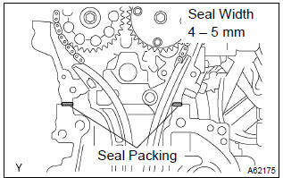
37. Install cylinder head cover sub–assy
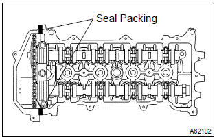
- Remove any old pacing (fipg) material.
- apply seal packing to 2 locations as shown in the illustration.
Seal packing: part no. 08826–00080 Or equivalent
N
otice
:
- remove any oil from the contact surface.
- Install the cylinder head cover within 3 minutes after applying seal packing.
- Do not put into engine oil 2 hours after installing.
- Install the cylinder head cover and 3 cable brackets with
the 9 bolts, 2 seal washers and 2 nuts. Uniformly tighten
the bolts and nuts, in the several passes.
Torque:
a 11 nvm (112 Kgf·cm, 8 ft·lbf) b 9.0 Nvm (92 Kgf·cm, 80 in.Vlbf)
38. Install ignition coil assy
- Install the 4 ignition coils with the 4 bolts.
Torque: 9.0 Nvm (92 Kgf·cm, 80 in.Vlbf)
39. Install engine wire
- Install the engine wire with the bolt and nut.
Torque: 9.0 Nvm (92 Kgf·cm, 80 in.Vlbf)
40. Install engine mounting insulator sub–assy rh

- Install the engine mounting insulator with the 4 bolts and
2 nuts.
Torque: 52 nvm (530 Kgf·cm, 38 ft·lbf)
41. Install generator assy
42. Install vane pump assy
43. Install cylinder head cover no.2

- Install the cylinder head cover with the 2 nuts and 2 clips.
Torque: 7.0 Nvm (71 Kgf·cm, 62 in.Vlbf)
44. Install front wheel rh torque: 103 nvm (1,050 Kgf·cm, 76 ft·lbf)
45. Add coolant
46. Check engine coolant leak
47. Check engine oil leak


Other materials:
Inspection procedure
Hint:
if different dtcs related to different systems that have terminal e2
as the ground terminal are output
simultaneously, terminal e2 may be open.
Read freeze frame data using the hand-held tester or the obd ii scan
tool. Freeze frame data records
the engine conditions when a malf ...
The ambient temperature does not display
Wiring diagram
Inspection procedure
1 Inspect outer ambient temperature sensor
Remove cooler (ambient temp. Sensor) thermistor.
measure resistance between terminals 1 and 2 of cooler
(ambient temp. Sensor) thermistor connector at each temperature.
Resistance:
at 0 c (0 f) ...
Replacement
Hint: components:
1. Precaution
2. Disconnect battery negative terminal
3. Remove horn button assy
Place the front wheels facing straight ahead.
using a torx socket wrench (t30), loosen the 2 torx
screws until the groove along the screw circumference
catches on the screw ca ...