Toyota Corolla (E120) 2002–2008 Repair Manual / Diagnostics / Supplemental restraint system / Short in side squib (rh) circuit (to
b+) / Inspection procedure
Toyota Corolla (E120): Inspection procedure
1 Check side squib(rh) circuit(airbag sensor assy center – front seat airbag assy rh)
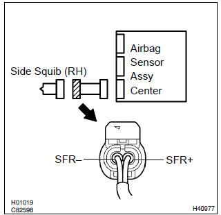
- Disconnect the negative (–) terminal cable from the battery, and wait at least for 90 seconds.
- disconnect the connectors between the airbag sensor assy center and the front seat airbag assy (rh).
- connect the negative (–) terminal cable to the battery, and wait at least for 2 seconds.
- turn the ignition switch to on.
- for the connector (on the front seat airbag assy side) between
the airbag sensor assy center and the front seat
airbag assy (rh), measure the voltage between sfr+
and body ground.
Ok: voltage: below 1 v

2 Check air bag sensor assy center
Sst 09843–18040
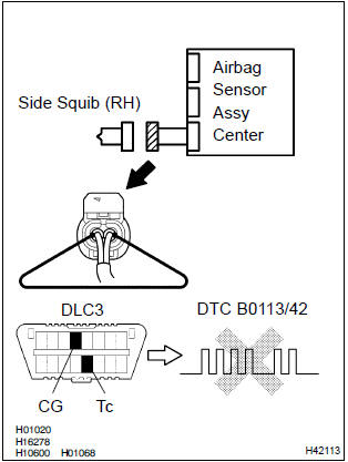
- Turn the ignition switch to lock.
- disconnect the negative (–) terminal cable from the battery, and wait at least for 90 seconds.
- connect the connector to the airbag sensor assy center.
- using a service wire, connect sfr+ and sfr– of the connector (on the front front seat airbag assy side) between the airbag sensor assy center and the front seat airbag assy (rh).
- connect the negative (–) terminal cable to the battery, and wait at least for 2 seconds.
- turn the ignition switch to on, and wait at least for 20 seconds.
- clear the dtc stored in memory .
- turn the ignition switch to lock, and wait at least for 20 seconds.
- turn the ignition switch to on, and wait at least for 20 seconds.
- check the dtc .
Ok: dtc b0113/42 is not output.
Hint
: codes other than code b0113/42 may be output at this time, but they are not relevant to this check.


3 Check side squib(rh)
Sst 09843–18040
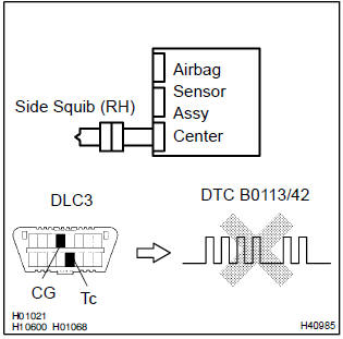
- Turn the ignition switch to lock.
- disconnect the negative (–) terminal cable from the battery, and wait at least for 90 seconds.
- connect the front seat airbag assy (rh) connector.
- connect the negative (–) terminal cable to the battery, and wait at least for 2 seconds.
- turn the ignition switch to on, and wait at least for 20 seconds.
- clear the dtc stored in memory .
- turn the ignition switch to lock, and wait at least for 20 seconds.
- turn the ignition switch to on, and wait at least for 20 seconds.
- check the dtc .
Ok: dtc b0113/42 is not output.
Hint
: codes other than code b0113/42 may be output at this time, but they are not relevant to this check.

4 Use simulation method to check


Replace all srs components including the wire harness


Other materials:
Replacement
Hint: components:
1. Precaution
2. Disconnect battery negative terminal
3. Remove instrument panel sub–assy lower
Remove the screw from the glove compartment door
stopper sub–assy.
pull the instrument panel sub–assy lower to remove it.
4. Separate passenger airbag co ...
On–vehicle inspection
1. Inspection throttle body idle speed control valve assy
Notice:
it is impossible to check the resister value and the operation
of isc valve by itself, because the isc valve
has an ic circuit inside it, which transforms the duty
signal from the ecm to the derive signal.
After check ...
Correct use of the seat
belts
Extend the shoulder belt so
that it comes fully over the
shoulder, but does not come
into contact with the neck or
slide off the shoulder.
Position the lap belt as low as
possible over the hips.
Adjust the position of the
seatback. Sit up straight and
well back in the seat.
Do not twist ...