Toyota Corolla (E120): Circuit description
The side squib (rh) circuit consists of the airbag sensor assy center and front seat airbag assy (rh).
It causes the srs to deploy when the srs deployment conditions are satisfied.
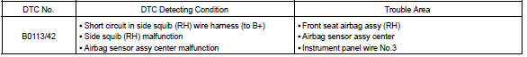
Dtc b0113/42 is recorded when a b+ short is detected in the side squib (rh) circuit.
Wiring diagram


Other materials:
Inspection procedure
1 Check d squib circuit(airbag sensor assy center – horn button
assy)
Disconnect the negative (–) terminal cable from the battery,
and wait at least for 90 seconds.
disconnect the connectors between the horn button assy
and the airbag sensor assy center.
for the blac ...
Seat belt pretensioners (front seats)
The pretensioners help the seat belts to quickly restrain the occupants by retracting
the seat belts when the vehicle is subjected to certain types of severe frontal
or side collision.
The pretensioners do not activate in the event of a minor frontal impact, a minor
side impact, a rear impact ...
Replacement
1. Disconnect battery negative terminal
2. Remove engine under cover rh
3. Remove starter assy
Disconnect the starter connector.
open the terminal cover.
remove the nut, then disconnect the starter wire.
remove the 2 bolts, then remove the starter.
4. Install starter a ...