Toyota Corolla (E120) 2002–2008 Repair Manual / Diagnostics / Sfi system / System too lean/rich / Inspection procedure
Toyota Corolla (E120): Inspection procedure
Hint
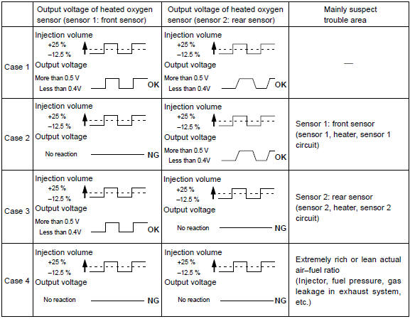
: hand–held tester only: narrowing down the trouble area is possible by performing ”a/f control” active test (heated oxygen sensor or other trouble areas can be distinguished).
- Perform active test using hand–held tester (a/f control).
Hint
: ”a/f control” is the active test which changes the injection volume to –12.5 % Or +25 %.
- Connect the hand–held tester to the dlc3 on the vehicle.
- Turn the ignition switch on.
- Warm up the engine by running the engine speed at 2,500 rpm for approximately 90 seconds.
- Select the item ”diagnosis / enhanced obd ii / active test / a/f control”.
- Perform ”a/f control” with the engine in an idle condition (press the right or left button).
Result
:
heated oxygen sensor reacts in accordance with increase and decrease of
injection volume
+25 % rich output: more than 0.5 V,
–12.5 % Lean output: less than 0.4 V
Notice
: there is a delay of few seconds in the sensor 1 (front sensor) output, and there is about 20 seconds delay at maximum in the sensor 2 (rear sensor).
The following of a/f control procedure enables the technician to check and graph the voltage outputs of both the heated oxygen sensors.
For displaying the graph indication, enter ”active test / a/f control / user data”, then select ”o2s b1s1 and o2s b1s2” by pressing ”yes” button and push ”enter” button before pressing ”f4” button.
Hint
:
- if different dtcs related to different systems that have terminal e2 as the ground terminal are output simultaneously, terminal e2 may be open.
- Read freeze frame data using the hand-held tester or the obd ii scan tool. Freeze frame data records the engine conditions when a malfunction is detected. When troubleshooting, it is useful for determining whether the vehicle was running or stopped, the engine was warmed up or not, the air–fuel ratio was lean or rich, etc. At the time of the malfunction.
- A high heated oxygen sensor (sensor 1) voltage (0.5 V or more) could
be caused by a rich air fuel mixture.
Check for conditions that would cause the engine to run rich.
- A low heated oxygen sensor (sensor 1) voltage (0.4 V or less) could
be caused by a lean air fuel mixture.
Check for conditions that would cause the engine to run lean.
1 Check air induction system
- Check the air induction system for vacuum leaks


2 Check connection of pcv hose


3 Inspect fuel injector assy(injection and volume)

4 Inspect mass air flow sensor
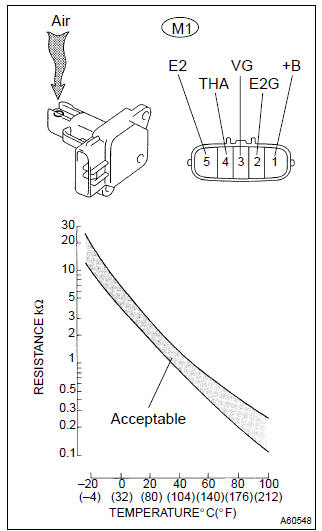
- Remove the mas air flow sensor.
- inspect output voltage.
- Apply battery voltage across terminals +b and e2g.
- Connect the positive (+) tester prove to terminal vg, and negative (–) tester prove to terminal e2g.
- Blow air into the mass air flow sensor, and check that the voltage fluctuates.
- resistance inspection.
- Measure the resistance between the terminals of the intake air temperature sensor.
Standard:
- Reinstall the mas air flow sensor.


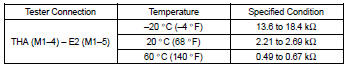
5 Inspect engine coolant temperature sensor(resistance)
- Remove the engine coolant temperature sensor.
- measure the resistance between the terminals of the engine coolant temperature sensor.
Standard:
Notice
: if you checking the engine coolant temperature sensor in water, be careful not to allow water to go into the terminals.
After checking, dry the sensor.
Hint
: alternate procedure: connect an ohmmeter to the installed engine coolant temperature sensor and read the resistance. Use an infrared thermometer to measure the engine temperature in the immediate vicinity of the sensor. Compare these values to the resistance/temperature graph. Change the engine temperature (warm up or allow to cool down) and repeat the test.
(C) reinstall the engine coolant temperature sensor.


6 Check for spark and ignition

7 Check fuel pressure
- Check the fuel pressure (high or low pressure).

8 Check for exhaust gas leakage
9 Read value of hand–held tester or obd ii scan tool(output voltage of heated oxygen sensor (bank 1 sensor 1))
- Connect the hand–held tester or the obd ii scan tool to the dlc3.
- start the engine and push the hand–held tester or the obd ii scan tool main switch on.
- select the item ”diagnosis / enhanced obd ii / data list / all / o2s b1s1”.
- warm up the heated oxygen sensor with the engine speed at 2,500 rpm for approximately 90 seconds.
- read the output voltage of the heated oxygen sensor during idling.
Heated oxygen sensor output voltage: alternates repeatedly between less than 0.4 V and more than 0.5 V (see the following table).


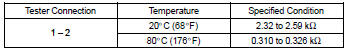
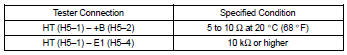
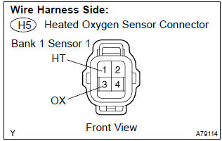
10 Inspect heated oxygen sensor(heater resistance)
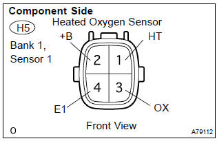
- Disconnect the h5 heated oxygen sensor connector.
- measure the resistance between the terminals of the heated oxygen sensor connector.
Standard:
- Reconnect the heated oxygen sensor connector.


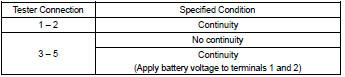
11 Inspect efi relay
- Remove the efi relay from the engine room r/b.
- check for continuity in the efi relay.
Standard:
- Reinstall the efi relay


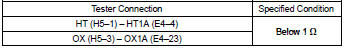
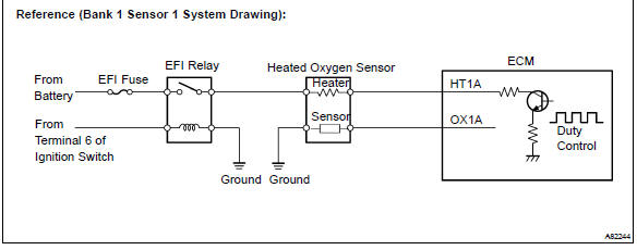
12 Check harness and connector(heated oxygen sensor – ecm)
- Disconnect the h5 heated oxygen sensor connector.
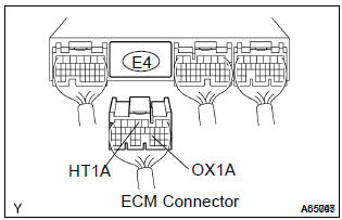
- disconnect the e4 ecm connector.
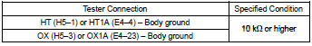
- check the resistance between the wire harness side connectors.
Standard (check for open):
Standard (check for short):
- Reconnect the ecm connector.
- reconnect the heated oxygen sensor connector.

13 Replace heated oxygen sensor
Hint
: check the air induction system for vacuum leaks.

14 Perform confirmation driving pattern
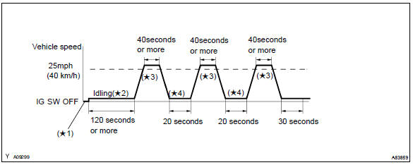
- Connect the hand–held tester to the dlc3. ( 1)
- switch the hand–held tester from the normal mode to the check mode . ( 1)
- start the engine and let it idle for 120 seconds or more. ( 2)
- drive the vehicle at 25 mph (40 km/h) or more for 40 seconds or more. ( 3)
- let the engine idle for 20 seconds or more. ( 4)
- perform steps (d) and (e) at least 3 times.
Hint
: if a malfunction exists, the mil will be illuminated on the multi–information display during step (f).
Notice
: if the conditions in this test are not strictly followed, detection of a malfunction will not occur. If you do not have the hand–held tester, turn the ignition switch off after performing steps from (c) to (f), then perform steps from (c) to (f) again.

15 Read output dtc(dtc p0171 and/or p0172 are output again)
- Connect the hand–held tester or the obd ii scan tool to the dlc3.
- turn the ignition switch on and push the hand–held tester or the obd ii scan tool main switch on.
- select the item ”diagnosis / enhanced obd ii / dtc info / current codes”.
- read the dtcs.
Result:


16 Confirm if vehicle has run out of fuel in past


Dtc is caused by running out of fuel (dtcs p0171 and/or p0172)
17 Perform confirmation driving pattern
Hint
: clear all dtcs prior to performing the confirmation driving pattern. (Refer to step 14)

18 Read output dtc(dtc p0171 and/or p0172 are output again)
- Connect the hand–held tester or the obd ii scan tool to the dlc3.
- turn the ignition switch on and push the hand–held tester or the obd ii scan tool main switch on.
- select the item ”diagnosis / enhanced obd ii / dtc info / current codes”.
- read the dtcs.
Result:


19 Replace heated oxygen sensor

20 Perform confirmation driving pattern
Hint
: clear all dtcs prior to performing the confirmation driving pattern. (Refer to step 14)
21 Read output dtc(dtc p0171 and/or p0172 are output again)
- Connect the hand–held tester or the obd ii scan tool to the dlc3.
- turn the ignition switch on and push the hand–held tester or the obd ii scan tool main switch on.
- select the item ”diagnosis / enhanced obd ii / dtc info / current codes”.
- read the dtcs.
Result:


22 Confirm if vehicle has run out of fuel in past


Dtc is caused by running out of fuel


Other materials:
Overhaul
1. Remove repair service starter kit
Remove the nut, then disconnect the lead wire from terminal
c.
Remove the 2 screws which are used to secure the repair
service starter kit to the starter drive housing.
remove the repair service starter kit.
remove the return ...
Precaution
1. Handling precautions on srs airbag system
The vehicle is equipped with srs (supplemental restraint system) such as
the driver airbag and front
passenger airbag. Failure to carry out service operation in correct sequence
could cause the srs to
unexpectedly deploy during servicing, po ...
Installing child restraints using a seat belt
■ Rear-facing - Infant seat/convertible seat
1 Place the child restraint system on the rear seat facing the rear of the vehicle.
2 Run the seat belt through the child restraint system and insert the plate into
the buckle. Make sure that the belt is not twisted.
3 Fully extend the shou ...