Toyota Corolla (E120) 2002–2008 Repair Manual / Diagnostics / Sfi system / System too lean/rich / Circuit description
Toyota Corolla (E120): Circuit description
The fuel trim is related to the feedback compensation value, not to the basic injection time. The fuel trim includes the short–term fuel trim and the long–term fuel trim.
The short–term fuel trim is the short–term fuel compensation used to maintain the air–fuel ratio at stoichiometric air–fuel ratio. The signal from the heated oxygen sensor indicates whether the air–fuel ratio is rich or lean compared to the stoichiometric air–fuel ratio. This variance triggers a reduction in the fuel volume if the air–fuel ratio is rich, and an increase in the fuel volume if it is lean.
The long–term fuel trim is the overall fuel compensation carried out in long–term to compensate for a continual deviation of the short–term fuel trim from the central value, due to individual engine differences, wear overtime and changes in the operating environment.
If both the short–term fuel trim and the long–term fuel trim are lean or rich beyond a certain value, it is detected as a malfunction and the mil is illuminated.
|
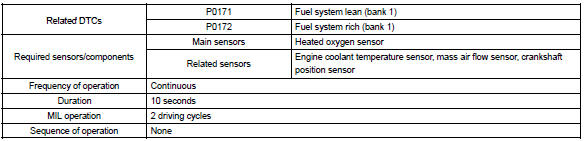
Dtc no. |
Dtc detection condition |
Trouble area |
| P0171 | When air–fuel ratio feedback is stable after warming up engine, fuel trim is considerably in error on lean side (2 trip detection logic) |
|
| P0172 | When air–fuel ratio feedback is stable after warming up engine, fuel trim is considerably in error on rich side (2 trip detection logic) |
|
Hint
:
- when dtc p0171 is recorded, the actual air–fuel ratio is on the lean side. When dtc p0172 is recorded, the actual air–fuel ratio is on the rich side.
- If the vehicle runs out of fuel, the air–fuel ratio is lean and dtc p0171 may be recorded. The mil then comes on.
- If the total of the short–term fuel trim value and long–term fuel trim value is within 35 % (engine coolant temperature is more than 75 c (167 f)), the system is functioning normally.
Monitor description
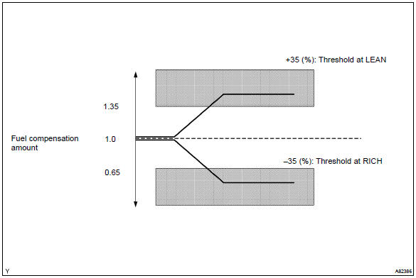
Under the closed–loop fuel control, fuel injection amounts that deviate from the ecm’s estimated fuel amount will cause a change in the long–term fuel trim compensation value. This long–term fuel trim is adjusted when there are persistent deviations in the short–term fuel trim values. And the deviation from a simulated fuel injection amount by the ecm affects a smoothed fuel trim learning value which is the combination of smoothed short–term fuel trim (fuel feedback compensation value) and smoothed long–term fuel trim (learning value of the air–fuel ratio). When the smoothed fuel trim learning value exceeds the dtc threshold, the ecm interprets this as a fault in the fuel system and sets a dtc.
Example: the smoothed fuel trim leaning value is more than +35% or less than –35%, the ecm interprets this as a fail in the fuel system.
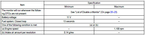
Monitor strategy
Typical enabling conditions
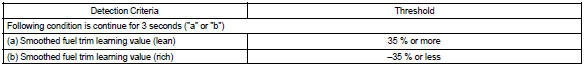
Typical malfunction thresholds
Wiring diagram
Refer to dtc p0130


Other materials:
Hood
Release the lock from the inside of the vehicle to open the hood.
1 Pull the hood lock release lever.
The hood will pop up slightly.
2 Pull up the auxiliary catch lever and lift the hood.
3 Hold the hood open by inserting the support rod into the slot.
CAUTION
■Pre-driving check
C ...
Circuit description
The d squib circuit consists of the airbag sensor assy center, spiral cable
sub–assy and horn button assy.
It causes the srs to deploy when the srs deployment conditions are satisfied.
Dtc b1180/17 is recorded when a short is detected in the d squib circuit (2nd
step).
Wiring diagra ...
Clock assy
Replacement
1. Remove console panel upper
2. Remove heater control knob
3. Remove instrument cluster finish panel
4. Remove clock assy
Using a screwdriver, disengage the 4 claws, remove the
clock as shown in the illustration.
Hint:
tape the screwdriver tip before use. ...