Toyota Corolla (E170): Starting the engine
1 Check that the parking brake is set.
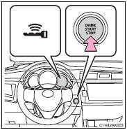
► Vehicles without a multi-information display
2 Continuously variable transmission: Check that the shift lever is set in P. Firmly depress the brake pedal.
Manual transmission: Check that the shift lever is set in N. Firmly depress the clutch pedal.
The smart key system indicator light (green) will turn on. If the indicator light does not turn on, the engine cannot be started.
3 Press the engine switch.
The engine will crank until it starts or for up to 30 seconds, whichever is less.
Continue depressing the brake pedal (continuously variable transmission) or clutch pedal (manual transmission) until the engine is completely started.
The engine can be started from any engine switch mode.
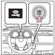
► Vehicles with a multi-information display
2 Continuously variable transmission: Check that the shift lever is set in P. Firmly depress the brake pedal.
Manual transmission: Check that the shift lever is set in N. Firmly depress the clutch pedal.
 will be displayed on the multi-information
display.
will be displayed on the multi-information
display.
If it is not displayed, the engine cannot be started.
3 Press the engine switch.
The engine will crank until it starts or for up to 30 seconds, whichever is less.
Continue depressing the brake pedal (continuously variable transmission) or clutch pedal (manual transmission) until the engine is completely started.
The engine can be started from any engine switch mode.


Other materials:
Audio & visual system
Preparation
Sst
Recomended tools
Equipment
...
Air conditioning controls
■ Adjusting the temperature setting
To adjust the temperature setting, turn
clockwise to increase the temperature
and turn counterclockwise to decrease
the temperature.
■ Fan speed setting
Press “>” on to increase the fan
speed.
Press “<” on to decrease the ...
Sound quality is bad in all modes (volume is too low)
Wiring diagram
Inspection procedure
1 Adjust sound quality
Adjust the sound quality.
Operate the radio receiver assy to adjust the sound quality.
Standard: malfunction disappear.
2 Compare it with another car of same model
Compare it with another vehicle of the same mo ...