Toyota Corolla (E210) 2019-2026 Owners Manual / Driving / Driving procedures / Selecting shift ranges in
the D position
Toyota Corolla (E210): Selecting shift ranges in the D position
To drive using temporary shift range selection, operate the "-" or "+" paddle shift switch.
When the "-" paddle shift switch is operated, the shift range switches to a range that enables engine braking force that is suitable to driving conditions. When the "+" paddle shift switch is operated, the shift range switches to a range that is one range higher than the current range.
Changing the shift range allows restriction of the highest gear, preventing unnecessary upshifting and enabling the level of engine braking force to be selected.
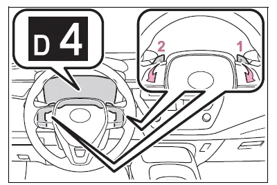
- Upshifting
- Downshifting
The selected shift range, from D1 to D10, will be displayed on the multi-information display.
■Gear step functions
- You can choose from 10 levels of engine braking force.
- A lower gear step will provide greater engine braking force than a higher gear step, and the engine speed will also increase.
■Deactivation of temporary 10-speed Sport Sequential Shiftmatic mode
In the following situations, temporary 10-speed Sport Sequential Shiftmatic mode will be deactivated:
- When the vehicle is stopped
- If the accelerator pedal is depressed continuously for more than a certain amount of time while in one gear range
- If the accelerator pedal is depressed abruptly and heavily
- When the shift lever is shifted to a position other than D
- When the "+" paddle shift switch is operated for a certain amount of time continuously


Other materials:
Front passenger occupant classification system
Your vehicle is equipped with a front passenger occupant classification system.
This system detects the conditions of the front passenger seat and activates or
deactivates the devices for the front passenger.
1 SRS warning light
2 Seat belt reminder light
3 “AIR BAG OFF” indicator light ...
On–vehicle inspection
1. Inspect for electrical door lock operation
Hint:
w/ power window:
the door control switch is built in the master switch in the driver’s door
and also in the passenger’s
door.
W/o power window:
the door control switch is in the driver’s door and also in the passenger’s
d ...
Pre–check
1. Diagnosis system
Release the parking brake lever.
check the warning lights.
When the ignition switch is turned on, check that the abs
warning light and brake warning light goes on for 3 sec.
Hint:
when the parking brake is applied or the level of the brake
fluid is low, the ...