Toyota Corolla (E210) 2019-2026 Owners Manual / For safety and security / Theft deterrent system / Engine immobilizer system
Toyota Corolla (E210): Engine immobilizer system
The vehicle's keys have built-in transponder chips that prevent the engine from starting if a key has not been previously registered in the vehicle's on-board computer.
Never leave the keys inside the vehicle when you leave the vehicle.
This system is designed to help prevent vehicle theft but does not guarantee absolute security against all vehicle thefts.
Operating the system
Vehicles without a smart key system
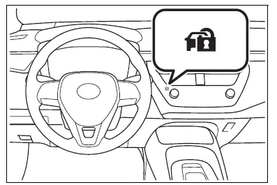
The indicator light flashes after the key has been removed from the engine switch to indicate that the system is operating.
The indicator light stops flashing after the registered key has been inserted into the engine switch to indicate that the system has been canceled.
Vehicles with a smart key system
The indicator light flashes after the engine switch has been turned off to indicate that the system is operating.
The indicator light stops flashing after the engine switch has been turned to ACC or ON to indicate that the system has been canceled.
■System maintenance
The vehicle has a maintenance- free type engine immobilizer system.
■Conditions that may cause the system to malfunction
- If the grip portion of the key is in contact with a metallic object
- If the key is in close proximity to or touching a key to the security system (key with a built-in transponder chip) of another vehicle
NOTICE
■To ensure the system operates correctly
Do not modify or remove the system.
If modified or removed, the proper operation of the system cannot be guaranteed.

Other materials:
Circuit description
The fuel trim is related to the feedback compensation value, not to the basic
injection time. The fuel trim includes
the short–term fuel trim and the long–term fuel trim.
The short–term fuel trim is the short–term fuel compensation used to maintain
the air–fuel ratio at stoichiomet ...
Body panel anti-rust agent (wax) application areas
Apply rustop w to the doors and hood edges (tips of outer panel folded parts)
and undersides, areas around
hinges, etc.To prevent rust. Coat the undersides of the edges using a nozzle and
air gun, and coat the areas around
the hinges using a brush.
Hint:
if rustop is unnecessarily ...
Circuit description
The p/t squib (lh) circuit consists of the airbag sensor assy center and seat
belt pretensioner (lh).
It causes the srs to deploy when the srs deployment conditions are satisfied.
Dtc b0135/73 is recorded when a short is detected in the p/t squib (lh) circuit.
Wiring diagram
...