Toyota Corolla (E210) 2019-2026 Owners Manual / Driving / Driving procedures / Changing gears in the M
position
Toyota Corolla (E210): Changing gears in the M position
To enter 10-speed sport sequential shiftmatic mode, shift the shift lever to M position.
Gear steps can then be selected by operating the shift lever or paddle shift switches, allowing you to drive in the gear step of your choosing.
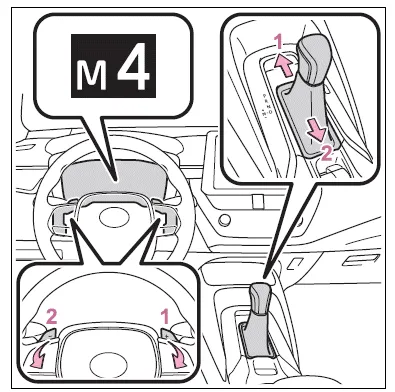
- Upshifting
- Downshifting
The gear changes once every time the shift lever or paddle shift switch is operated.
The selected gear step, from M1 to M10, will be displayed on the multi-information display.
However, even when in the M position, the gear steps will be automatically changed if the engine speed is too high, or too low.
■Gear step functions
- You can choose from 10 levels of engine braking force.
- A lower gear step will provide greater engine braking force than a higher gear step, and the engine speed will also increase.
■When the vehicle comes to a stop with the shift lever in the M position
- The transmission will automatically downshift to M1 once the vehicle is stopped.
- After a stop, the vehicle will start off in M1.
- When the vehicle is stopped, the transmission is set at M1.
■Downshifting restriction warning buzzer
To help ensure safety and driving performance, downshifting operation may sometimes be restricted. In some circumstances, downshifting may not be possible even when the shift lever or paddle shift switch is operated. (A buzzer will sound twice.)
■If the 10-speed sport sequential shiftmatic mode indicator does not come on even after shifting the shift lever to M
This may indicate a malfunction in the continuously variable transmission system. Have the vehicle inspected by your Toyota dealer immediately.
(In this situation, the transmission will operate in the same manner as when the shift lever is in D.)
■Continuously variable transmission fail-safe control
The system detects malfunctioning parts targeted (all of the solenoids that perform the shifting function) by the On-Board Diagnostics, and performs fail-safe mechanisms, such as restricting the shifting function or transmission ratio control.
In this event, the malfunction indicator lamp turns on.


Other materials:
Front passenger occupant classification system
Your vehicle is equipped with a front passenger occupant classification system.
This system detects the conditions of the front passenger seat and activates or
deactivates the devices for the front passenger.
1 SRS warning light
2 Seat belt reminder light
3 “AIR BAG OFF” indicator light ...
Air outlets
■ Location of air outlets
The air outlets and air volume changes according to the selected airflow mode.
: Some models
■ Adjusting the position of and opening and closing the air outlets
► Front center outlets
Direct air flow to the left or right, up or down.
► Fron ...
If a warning message is displayed
The multi-information display
shows warnings for
system malfunctions and
incorrectly performed operations,
and messages that
indicate a need for maintenance.
When a message is
displayed, perform the
appropriate corrective
action for the message.
If a warning message is displayed
again after the
ap ...