Toyota Corolla (E120) 2002–2008 Repair Manual / Diagnostics / Supplemental restraint system / Short in d squib circuit (to ground) / Inspection procedure
Toyota Corolla (E120): Inspection procedure
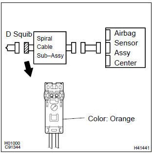
1 Check d squib circuit(airbag sensor assy center – horn button assy)
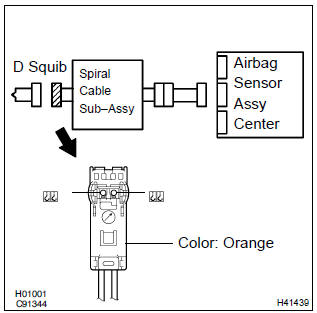
- Disconnect the negative (–) terminal cable from the battery, and wait at least for 90 seconds.
- disconnect the connectors between the airbag sensor assy center and the horn button assy.
- for the orange connector (on the spiral cable sub–assy
side) between the horn button assy and the spiral cable
sub–assy, measure the resistance between d+ and body
ground.
Ok: resistance: 1 mw or higher


2 Check air bag sensor assy center
Sst 09843–18040
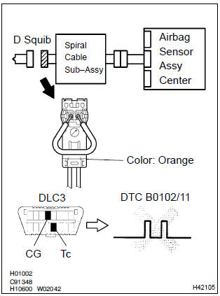
- Connect the connector to the airbag sensor assy center.
- using a service wire, connect d+ and d– of the orange connector (on the spiral cable sub–assy side) between the horn button assy and the spiral cable sub–assy.
- connect the negative (–) terminal cable to the battery, and wait at least for 2 seconds.
- turn the ignition switch to on, and wait t least for 20 seconds.
- clear the dtc stored in memory .
- turn the ignition switch to lock, and wait at least for 20 seconds.
- turn the ignition switch to on, and wait at least for 20 seconds.
- check the dtc .
Ok: dtc b0102/11 is not output.
Hint
: codes other than code b0102/11 may be output at this time, but they are not relevant to this check.


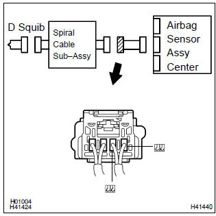
3 Check d squib
Sst 09843–18040

- Turn the ignition switch to lock.
- disconnect the negative (–) terminal cable from the battery, and wait at least for 90 seconds.
- connect the horn button assy connectors.
- connect the negative (–) terminal cable to the battery, and wait at least for 2 seconds.
- turn the ignition switch to on, and wait at least for 20 seconds.
- clear the dtc stored in memory .
- turn the ignition switch to lock, and wait at least for 20 seconds.
- turn the ignition switch to on, and wait at least for 20 seconds.
- check the dtc .
Ok: dtc b0102/11 is not output.
Hint
: codes other than code b0102/11 may be output at this time, but they are not relevant to this check.


4 Use simulation method to check


Replace all srs components including the wire harness
5 Check instrument panel wire(airbag sensor assy center – spiral cable sub–assy)
- Disconnect the connector of the instrument panel wire.
- for the connector (on the spiral cable sub–assy side) between
the airbag sensor assy center and the spiral cable
sub–assy, measure the resistance between d+ and body
ground.
Ok: resistance: 1 mΩ or higher

6 Check spiral cable sub–assy
- For the orange connector (on the spiral cable sub–assy
side) between the horn button assy and the spiral cable
sub–assy, measure the resistance between d+ and body
ground.
Ok: resistance: 1 mΩ or higher


7 Use simulation method to check


Replace all srs components including the wire harness


Other materials:
Warning light and warning buzzer list
*1: Parking brake engaged warning buzzer:
*2: Open door warning buzzer:
*3: Vehicles with a drive monitor display
*4: Vehicles with a multi-information display
*5: Driver’s seat belt buzzer:
Vehicles without a smart key system: The driver’s seat belt buzzer sounds to alert
the d ...
Inspection procedure
1 Check front airbag sensor (rh) circuit (to b+)(airbag sensor assy
center – airbag front rh sensor)
Disconnect the negative (–) terminal cable from the battery,
and wait at least for 90 seconds.
disconnect the connectors between the airbag front rh
sensor and the airbag sen ...
Disposal
Hint:
when scrapping vehicle equipped with an srs or disposing of a horn button assy,
always first deploy the
airbag in accordance with the procedure described below. If any abnormality
occurs in the airbag deployment,
contact the service dept. Of toyota motor sales, u.S.A., Inc.
Caution:
...