
Toyota Corolla (E120) 2002–2008 Repair Manual / Diagnostics / Electronic controlled automatic transaxle / Shift solenoid ”a” performance
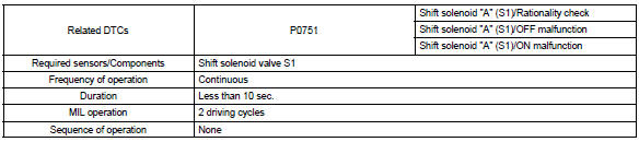
(shift solenoid valve s1)
Toyota Corolla (E120): Shift solenoid ”a” performance (shift solenoid valve s1)
Dtc p0751 shift solenoid ”a” performance (shift solenoid valve s1)
System description
The ecm uses signals from the vehicle speed sensor and crankshaft position sensor to detect the actual gear position (1st, 2nd, 3rd or o/d gear).
Then the ecm compares the actual gear with the shift schedule in the ecm memory to detect the mechanical trouble of the shift solenoid valves, the valve body or automatic transaxle (clutch, brake or gear etc.).

Monitor description
The ecm commands gear shifts by turning the shift solenoid valves ”on/off”. According to the input shaft revolution, intermediate (counter) shaft revolution and output shaft revolution, the ecm detects the actual gear position (1st, 2nd, 3rd or o/d gear position). When the gear position commanded by the ecm and the actual gear position are not same, the ecm illuminates the mil.
Monitor strategy
Typical enabling conditions
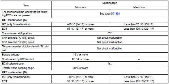
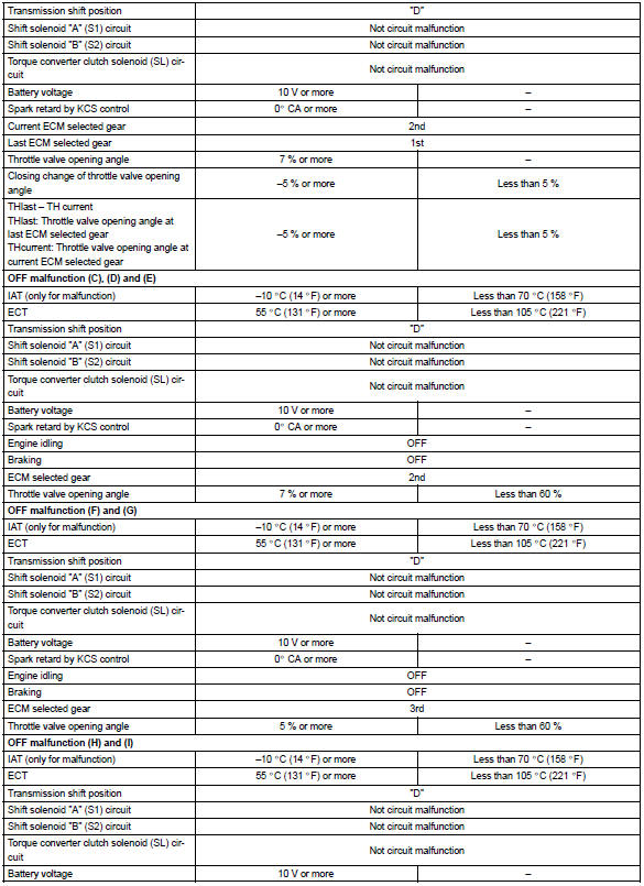
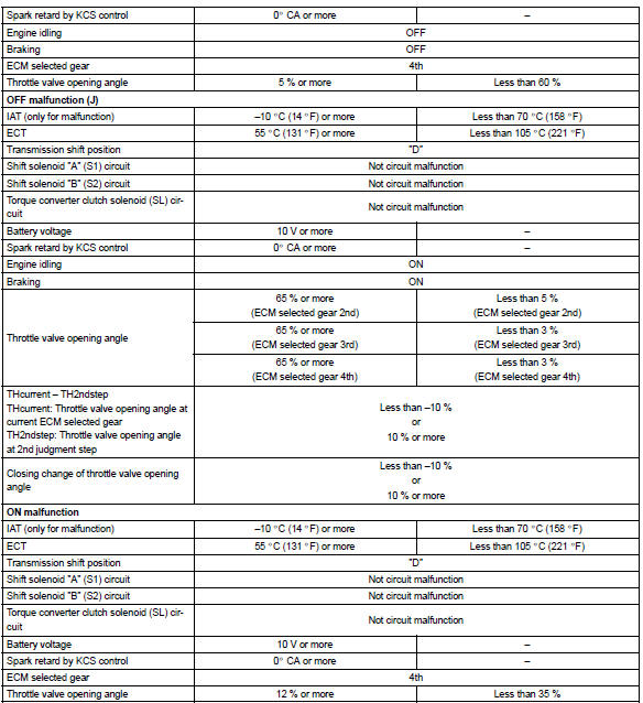
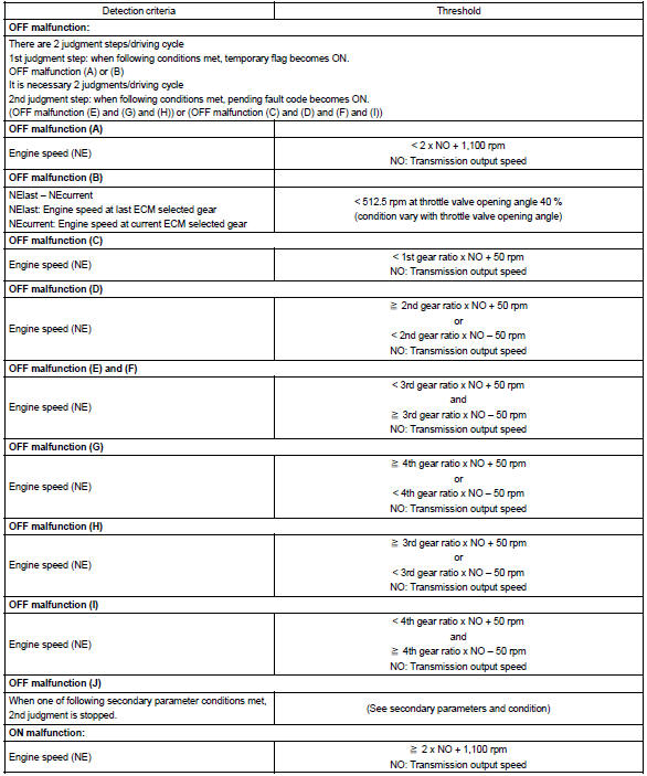
Typical malfunction thresholds


Other materials:
Combination meter assy
Overhaul
Hint: components:
1. Remove meter hood sub–assy
2. Remove combination meter assy
Remove the screw.
disengage the 2 clips as shown in the illustration.
disconnect the connector, then remove the combination
meter.
3. Remove combination meter glass
Di ...
Automatic transaxle fluid (atm)
On–vehicle inspection
1. Check the fluid level
Hint:
drive the vehicle so that the engine and transaxle are at normal
operating temperature.
Fluid temperature: 70 – 80 °c (158 – 176 °f)
park the vehicle on a level surface and set the parking
brake.
with the engin ...
Problem symptoms table
Proceed to the reference page shown in the table below for each malfunction
symptom and troubleshoot
each circuit.
Hint:
troubleshooting of the tvip system is based on the premise that the door lock
control system and wireless
door lock control system is operating normally. Accordingly, be ...