Toyota Corolla (E120): Replacement
Hint
: installation is according to the reverse order of the removal.
1. Remove fr wiper arm rh
2. Remove fr wiper arm lh
3. Remove hood to cowl top seal
4. Remove cowl top ventilator louver lh
5. Remove cowl top ventilator louver rh
6. Remove front door weatherstrip rh
7. Remove front door weatherstrip lh
8. Remove front pillar garnish rh
9. Remove front pillar garnish lh
10. Remove inner rear view mirror assy
11. Remove rh visor assy
12. Remove lh visor assy
13. Remove glove box lamp assy
14. Remove assist grip sub–assy
15. Remove visor holder
16. Remove roof headlining assy
17. Remove roof drip side finish moulding center rh
18. Remove roof drip side finish moulding center lh
19. Remove windshield moulding outside
- Using a knife, cut off the moulding as shown in the illustration.
Notice
: do not damage the body with the knife.
- remove the remaining moulding.
Hint
: when removing, make a cut partly, pull and remove it by hand.
20. Remove windshield glass
Hint
: depending on a vehicle type, either a 1–piece type or a 2–piece type of stopper is installed.
- push a piano wire through between the body and glass from the interior.
Hint
: apply protective tape to the outer surface to keep the surface from being scratched.
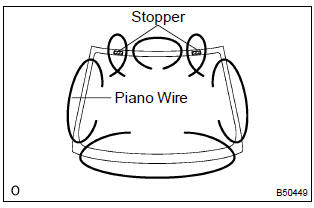
- Tie both wire ends to wooden blocks or similar objects.
Notice
:
- when separating the glass, take care not to damage the paint and interior/exterior ornaments.
- To prevent the piano wire to be cut, do not cross it.
- cut the adhesive by pulling the piano wire around it.
- using a suction rubber, remove the glass.
Notice
: leave as much adhesive on the body as possible when cutting off the glass.
21. Clean windshield glass
- Using a scraper, remove the damaged stoppers, dam and adhesive sticking to the glass.
- clean the outer circumference of the glass with white gasoline.
Notice
:
- do not touch the glass after cleaning it.
- Be careful not to damage the body.
22. Install windshield glass stopper no.1
- install 2 new windshield glass stoppers no.1 To the body.
23. Install windshield glass stopper no.2
- Coat the installation part of the stopper with primer g.
Notice
:
- dry the primer coating for 3 minutes or more.
- Do not apply too much primer.
- install 2 new windshield glass stoppers no.2 Onto the
glass as shown in the illustration.
A: 40.0 Mm (1.575 In.)
B: 7.7 Mm (0.303 In.)
24. Install front pillar outer dam
- coat the installation part of the front pillar outer dam with primer g.
Notice
:
- dry the primer coating for 3 minutes or more.
- Do not apply too much primer.
- install 2 new front pillar outer dams with double–stick tape as shown in the illustration.
Notice
:
do not touch the glass face after cleaning it.
A: 7 mm (0.28 In.)
B: 22.5 Mm (0.886 In.)
C: 45 mm (1.77 In.)
D: 5 mm (0.20 In.)
25. Install windshield glass
- Clean and shape the contact surface of the vehicle’s body.
- Using a knife, cut away any rough areas on the body.
Hint
: leave as much adhesive on the body as possible.
- Clean the cut surface of the adhesive with a piece of shop rag saturated in cleaner.
- position the glass.
- Using a suction rubber, place the glass in the correct position.
- Check that all the contacting parts of the glass rim are perfectly even.
- Place reference marks between the glass and body.
Notice
: check that the stoppers are attached to the body correctly.
Hint
: when reusing the glass, check and correct the reference mark’s positions.
- Remove the glass.
- coat the contact surface of the body panel with primer m.
- using a brush, coat the exposed part of the contact surface on the vehicle side with primer m.
Notice
:
- dry the primer coating for 3 minutes or more.
- Do not coat the adhesive with primer m.
- Do not apply too much primer.
- coat the contact surface of the glass with primer g.
- Using a brush or sponge, coat the edge of the glass and the contact surface with primer g.
Notice
:
- dry the primer coating for 3 minutes or more.
- Do not apply too much primer.
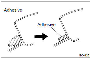
- Apply adhesive.
- Cut off the tip of the cartridge nozzle as shown in the
illustration.
Part no. 08850–00801 Or equivalent
Hint
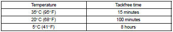
: after cutting off the tip, use all adhesive within the time described in the table below.
- Load the sealer gun with the cartridge.
- Coat the glass with adhesive, as shown in the illustration.
A: 8.0 Mm (0.315 In.) Or more b: 12.5 Mm (0.492 In.) Or more
- install the glass.
- Using a suction rubber, position the glass so that the reference marks are aligned, and press it in gently along the rim.
Notice
:
- dry the primer coating for 3 minutes or more.
- Check that the stoppers are attached to the body correctly.
- Check the clearance between the body and glass.
- Lightly press the glass front surface for close contact.
- Using a scraper, remove any excess or protruding adhesive.
Hint
: apply adhesive on the glass rim.
26. Install windshield moulding outside
- install a new windshield moulding to the windshield glass before the adhesive has hardened.
- hold the windshield glass in place securely with protective tape or equivalent until the adhesive has completely hardened.
- Using a scraper, remove any excess or protruding adhesive before the adhesive has hardened.
Notice
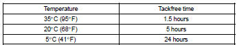
: take care not to drive the vehicle during the time described in the table below.
27. Inspect for leak and repair
- conduct a leak test after the adhesive has completely hardened.
- seal any leak with sealant.


Other materials:
Capacity and distribution
Cargo capacity depends on the total weight of the occupants.
(Cargo capacity) = (Total load capacity) — (Total weight of occupants)
Steps for Determining Correct Load Limit —
(1) Locate the statement “The combined weight of occupants and cargo should never
exceed XXX kg or XXX lbs.” on ...
Circuit description
The speed sensor detects wheel speed and transmits the appropriate
signals to the ecu. These signals are used for control
of the abs control system. Each of the front and rear rotors has
48 serrations.
When the rotors rotate, the magnetic field generated by the permanent
magnet in the spe ...
Inspection procedure
1 Inspect fuse(stop)
Turn the ignition switch to off.
remove the stop fuse from the instrument panel j/b.
check continuity of the stop fuse.
Ok: continuity
2 Inspect stop lamp switch assy
Disconnect the stop lamp switch assy connector.
check continuity betw ...