Toyota Corolla (E120) 2002–2008 Repair Manual / Diagnostics / Sfi system / Ignition coil primary/secondary
circuit / Circuit description
Toyota Corolla (E120): Circuit description
Hint
:
- these dtcs indicate a malfunction related to the primary circuit.
- If dtc p0351 is displayed, check the no.1 Ignition coil with igniter circuit.
- If dtc p0352 is displayed, check the no.2 Ignition coil with igniter circuit.
- If dtc p0353 is displayed, check the no.3 Ignition coil with igniter circuit.
- If dtc p0354 is displayed, check the no.4 Ignition coil with igniter circuit.
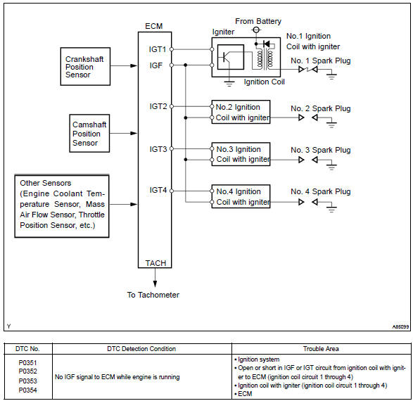
A direct ignition system (dis) is used on this vehicle. The dis improves the ignition timing accuracy, reduces high–voltage loss, and enhances the overall reliability of the ignition system by eliminating the distributor.
The dis is a 1–cylinder ignition system which ignites one cylinder with one ignition coil. In the 1–cylinder ignition system, the one spark plug is connected to the end of the secondary winding. High voltage generated in the secondary winding is applied directly to the spark plug. The spark of the spark plug passes from the center electrode to the ground electrode.
The ecm determines the ignition timing and outputs the ignition signals (igt) for each cylinder. Using the ignition (igt) signal, the ecm turns on and off the power transistor inside the igniter and this switches on and off the current to the primary coil. When the current flow to the primary coil is cut off, high–voltage is generated in the secondary coil and this voltage is applied to the spark plugs to spark inside the cylinders.
As the ecm cuts the current to the primary coil, the igniter sends back the ignition confirmation (igf) signal for each cylinder ignition to the ecm.
Monitor description
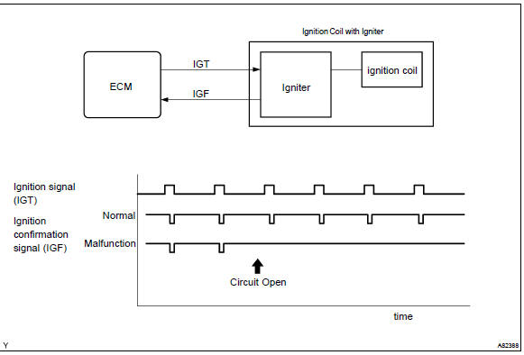
If the ecm does not receive the ignition confirmation signal (igf) after sending the ignition signal (igt), it interprets this as a fault in the igniter and sets a dtc.
Monitor strategy
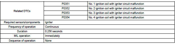
Typical enabling conditions
Typical malfunction thresholds

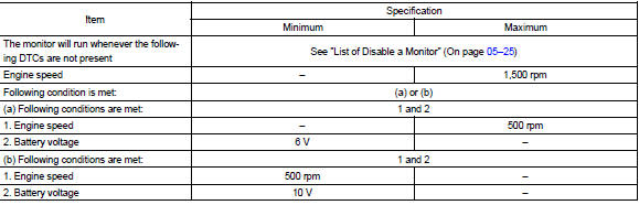
Component operating range

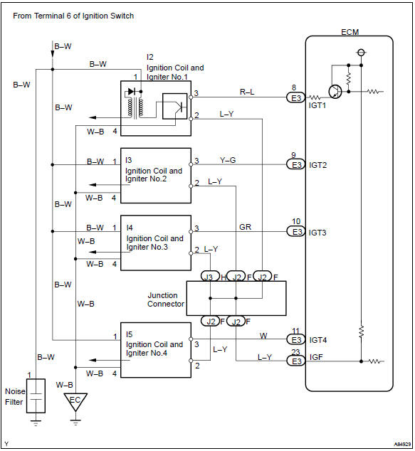
Wiring diagram


Other materials:
How to register a Bluetooth® device
1 Display the “Bluetooth* Setup” screen. *: Bluetooth is a registered trademark
of Bluetooth SIG, Inc.
2 Select “Add”.
3 When this screen is displayed, search for the device name displayed on this
screen on the screen of your Bluetooth® device.
For details about operating the Bluetoo ...
Inspection procedure
Hand–held tester:
1 Check operation of stop light
Check if the stop lights go on and off normally when the brake pedal is
depressed and released.
2 Inspect stop light switch assy
Check the resistance between the terminals when the
switch is turned on and off.
Standard:
...
Communication system
Horn system
Location
Problem symptoms table
Inspection
1. Inspect low pitched horn assy
Connect the positive (+) lead from the battery to the terminal
and the negative (–) lead to the horn body, and check
that the horn blows.
If the result is not as specified, replace the ...