Toyota Corolla (E120) 2002–2008 Repair Manual / Audio & visual / Radio receiver assy
Toyota Corolla (E120): Radio receiver assy
Replacement
Рint
: components:
1. Remove floor shift shift lever knob sub–assy (m/t transaxle)
2. Remove console panel upper
3. Remove heater control knob
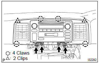
4. Remove instrument cluster finish panel
5. Remove instrument cluster finish panel sub–assy center
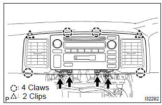
- Remove the 4 screws.
- using a screwdriver, disengage the 2 clips and 4 claws,
then remove the instrument cluster finish panel sub–assy
center with radio receiver assy.
Hint
: tape the screwdriver tip before use.
- disconnect the connectors.
6. Remove radio receiver assy
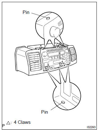
- Disengage the 4 claws and 6 pins.
- remove the radio receiver assy from the instrument cluster finish panel sub–assy center.
7. Remove radio bracket no.1
- Remove the 4 screws and radio bracket no. 1.
8. Remove radio bracket no.2
- remove the 4 screws and radio bracket no. 2.
9. Install instrument cluster finish panel sub–assy center
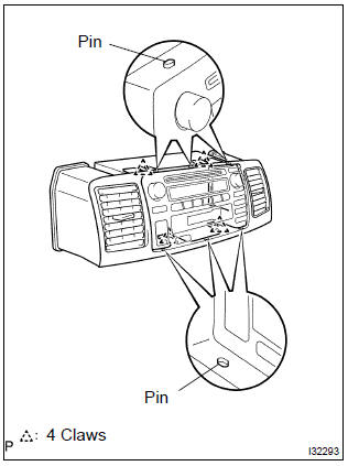
- Place the radio receiver assy temporarily on the instrument panel sub–assy upper. (*1)
- under the condition of (*1), engage the 6 pins and 4 claws of the radio receiver assy with the instrument cluster finish panel sub–assy center. (*2)
- under the condition of (*2), slide the instrument cluster finish panel sub–assy center and the radio receiver assy forward of the vehicle.
- Connect the connectors and install the 2 clips and 4 claws.
- install the 4 screws and instrument cluster finish panel sub–assy center with radio receiver assy.


Other materials:
Inspection
1. Charcoal canister assy
Visually check the charcoal canister for cracks or damage.
Inspect the charcoal canister operation.
Plug the vent port with the cap.
While holding the purge port closed, blow air (1.76
Kpa, 18 gf/cm2, 0.26 Psi) into the evap port and
...
Circuit description
The seat position sensor circuit consists of the airbag sensor assy center
and seat position sensor.
Dtc b1153/25 is recorded when a malfunction is detected in the seat position
sensor circuit.
Wiring diagram
...
Overhaul
1. Inspect 1st gear thrust clearance
Using a feeler gauge, measure the 1st gear thrust clearance.
Standard clearance:
0.10 – 0.40 Mm (0.0039 – 0.0157 In.)
2. Inspect 2nd gear thrust clearance
Using a dial indicator, measure the 2nd gear thrust clearance.
Standard clearan ...