Toyota Corolla (E120) 2002–2008 Repair Manual / Audio & visual / Front no.1 Speaker assy
Toyota Corolla (E120): Front no.1 Speaker assy
Replacement
Hhint
: components:
1. Remove front armrest assy lh
2. Remove power window regulator master switch assy (w/ power window)
3. Remove front armrest base panel upper lh (w/o power window)
4. Remove front door window regulator handle assy (w/o power window)
5. Remove front door lower frame bracket garnish lh
6. Remove front door trim board sub–assy lh
7. Remove front no.1 Speaker assy
- Disconnect the connector.
- using a rivet cutter and air drill, drill out the rivets and remove the front no.1 Speaker assy.
Notice
:
- prizing the hole with a drill can lead to damage to the rivet hole or breaking the drill.
- Take care as the cut rivet is hot.
Hint
: even if flange is taken off, continue drilling and push out remaining fragments will the drill.
- using a vacuum cleaner, remove the drilled rivet and their dust from the inside of the door.
8. Install front no.1 Speaker assy
- Using an air riveter and nose piece no.1, Strike rivets into the door panel to install the front no.1 Speaker assy to the door panel.
Notice
: install them in the order shown in the illustration.
Notice
:
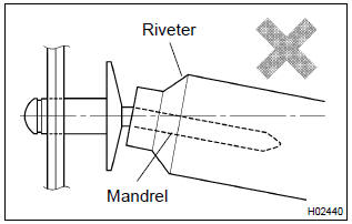
- do not prize a riveter, as riveter is damaged, it is not
- tightened and the mandrel is bent.
- Do not tilt the riveter and disconnect the rivet from the material while handling a riveter, as the materials are not tightened firmly.
- Install the rivet while attaching materials, as they are not tightened firmily.
- connect the connector.
9. Install front door window regulator handle assy (w/o power window)


Other materials:
Inspection procedure
1 Check side squib(lh) circuit(airbag sensor assy center – front
seat airbag assy lh)
Disconnect the negative (–) terminal cable from the battery,
and wait at least for 90 seconds.
disconnect the connectors between the airbag sensor
assy center and the front seat airbag assy ...
Overhaul
1. Drain brake fluid
Notice:
wash the brake fluid off immediately if it comes into contact with any painted
surface.
2. Remove air cleaner cap sub–assy
3. Remove brake master cylinder sub–assy
disconnect the brake fluid level switch connector from
master cylinder reservoir subâ ...