Toyota Corolla (E120): Pre–check
1. Diagnosis system
- Release the parking brake lever.
- check the warning lights.
When the ignition switch is turned on, check that the abs warning light and brake warning light goes on for 3 sec.
Hint
: when the parking brake is applied or the level of the brake fluid is low, the brake warning light is lit.
If the indicator check result is not normal, proceed to troubleshooting for the abs warning light circuit or brake warning light circuit ().
- In case of not using hand–held tester: check the dtc.
- Using sst, it connects terminal tc and cg of dlc3.
Sst 09843–18040
- turn the ignition switch to on.
- Read the dtc from the abs warning light on the combination meter.
Hint
:
- if not code appears, inspect the diagnostic circuit or abs warning light circuit.
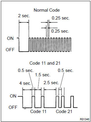
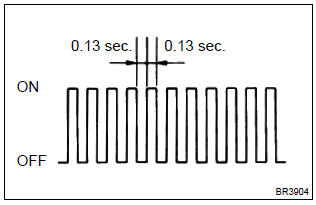
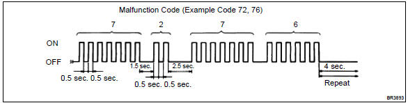
- As an example, the blinking patterns for normal code and codes 11 and 21 are shown on the left.
- Codes are explained in the code table.
If 2 or more malfunctions are indicated at the same time, the lowest numbered dtc will be displayed 1st.
- After completing the check, remove the sst from
the dlc3.
Sst 09843–18040
- in case of using hand–held tester: check the dtc.
- Read the dtc by following the prompts on the tester screen.
Hint
: please refer to the hand–held tester operator’s manual for further details.
- in case of not using hand–held tester: clear dtc.
- Using sst, it connects the terminal tc and cg of the
dlc3.
Sst 09843–18040
- turn the ignition switch to on.
- Clear dtc stored in ecu by depressing the brake pedal 8 or more times whitin 5 sec.
- Check that the abs warning light shows the normal code.
- Remove the sst from the dlc3.
Sst 09843–18040
Hint
: disconnect the battey cable during repairs will not erase the dtc in the ecu.
- in case of using hand–held tester: clear the dtc.
- Turn the ignition switch to on.
- Operate the hand–held tester to erase the codes.
Hint
: please refer to the hand–held tester operator’s manual for further details.
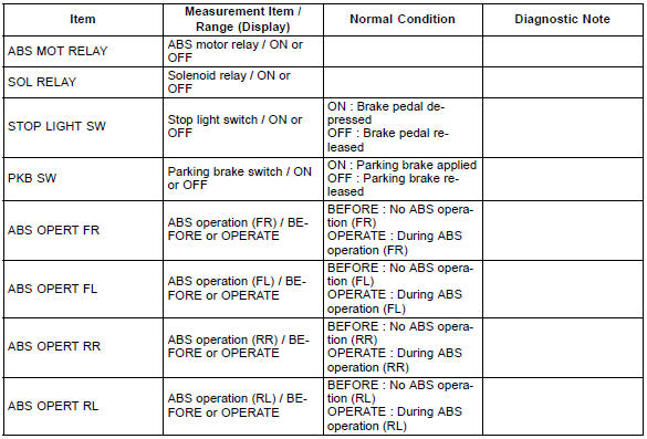
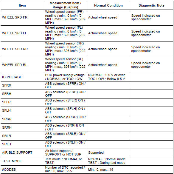
2. Data list
Hint
: according to the data list displayed by the hand–held tester, you can read the value of the switch, sensor, actuator and so on without parts removal. Reading the data list as a first step of troubleshooting is one of the method to shorten the labor time.
- Connect the hand–held tester to the dlc3.
- turn the ignition switch to on.
- according to the display on tester, read the ”data list”.
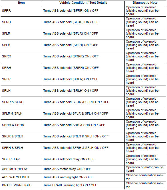
3. Active test
Hint
: performing the active test using the hand–held tester allows the relay, actuator and so on to operate without parts removal. Performing the active test as a first step of troubleshooting is one of the methods to shorten the labor time.
It is possible to display the data list during the active test.
- Connect the hand–held tester to the dlc3.
- turn the ignition switch to on.
- according to the display on tester, perform the ”active test”.
4. Freeze frame data
- The vehicle (sensor) status memorized during abs operation or at the time of error code detection can be displayed using the hand–held tester.
- only one record of freeze frame data is stored and the freeze frame data generated during abs operation are constantly updated. Also, the number of the ignition switch’s ”on” after the freeze frame data is stored can be memorized up to 31 and it can be displayed.
Hint
: if the ignition switch ”on” operation exceeds 31 times, ”31” appears on the display.
- If the diagnosis code abnormality occurs, the freeze frame data at the occurrence of the abnormality is stored but the abs actuation data is deleted.
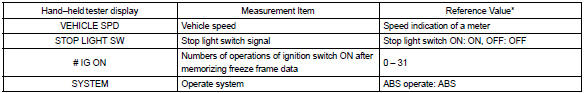
*: If no conditions are specifically stated for ”idling”, it means the shift lever is at n or p position, the a/c switch is off and all accessory switches are off.
5. Speed sensor signal check
Hint
: if the ignition switch is turned from on to acc or lock during test mode, dtc will be erased.
- in case of not using hand–held tester: check the speed sensor signal.
- Turn the ignition switch to on.
- Using sst, it connects the terminal ts and cg of
dlc3.
Sst 09843–18040
- start the engine.
- Check that the abs warning light blinks.
Hint
: if the abs warning light does not blink, inspect the abs warning light circuit and ts circuit ( or 05–335).
- Drive the vehicle straight forward at the speed of 45
km/h (28 mph) or over for several seconds and
check that the abs warning light comes off.
Hint
: the sensor check may not be completed if the wheels spin or the steering wheels steered during check.
- Stop the vehicle.
- Using sst, it connects the terminal tc and cg of the
dlc3.
Sst 09843–18040
- read the number of blinks of the abs warning light.
Hint
:
- see the list of dtc shown on the 05–303.
- If every sensor is normal, a normal code is output (a cycle of 0.25 Sec. On and 0.25 Sec. Off is repeated).
- If 2 or more malfunctions are indicated at the same time, the lowest numbered code will be displayed.
- After performing the check, turn the ignition switch
to off, and remove the sst from the dlc3.
Sst 09843–18040
- in case of using hand–held tester: check the speed sensor signal.
- Do step (3) to (6) on the previous page.
- Read the dtc by following the prompts on the tester screen.
Hint
: please refer to the hand–held tester operator’s manual for further details.


Other materials:
Inspection procedure
Hint:
read freeze frame data using the hand-held tester or the obd ii scan tool.
Freeze frame data records the
engine conditions when a malfunction is detected. When troubleshooting, it is
useful for determining whether
the vehicle was running or stopped, the engine was warmed up or not, the ...
Inspection procedure
1 Check harness and connector(transmission control switch –
body ground)
Disconnect the transmission control switch connector of
shift lever assy.
measure the resistance according to the value(s) in the
table below.
Standard:
2 Inspect transmission control switch
M ...
Inspection procedure
1 Check p squib circuit(airbag sensor assy center – instrument
panel passenger airbag assy)
Disconnect the negative (–) terminal cable from the battery,
and wait at least for 90 seconds.
disconnect the connectors between the airbag sensor
assy center and the instrument panel ...