Toyota Corolla (E120) 2002–2008 Repair Manual / Diagnostics / Supplemental restraint system / Short in p squib circuit (to b+) / Inspection procedure
Toyota Corolla (E120): Inspection procedure
1 Check p squib circuit(airbag sensor assy center – instrument panel passenger airbag assy)
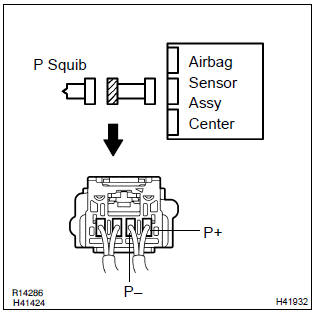
- Disconnect the negative (–) terminal cable from the battery, and wait at least for 90 seconds.
- disconnect the connectors between the airbag sensor assy center and the instrument panel passenger airbag assy.
- connect the negative (–) terminal cable to the battery, and wait at least for 2 seconds.
- turn the ignition switch to on.
- for the connector (on the instrument panel passenger airbag
assy side) between the airbag sensor assy center
and the instrument panel passenger airbag assy, measure
the voltage between p+ and body ground.
Ok: voltage: below 1 v

2 Check air bag sensor assy center
Sst 09843–18040
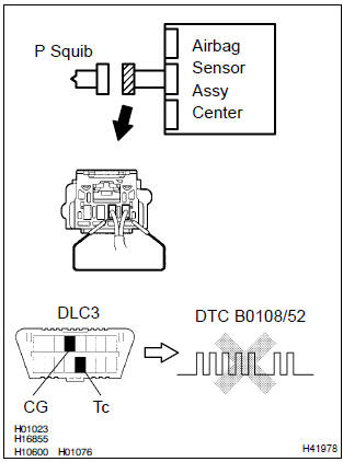
- Turn the ignition switch to lock.
- disconnect the negative (–) terminal cable from the battery, and wait at least for 90 seconds.
- connect the connector to the airbag sensor assy center.
- using a service wire, connect p+ and p– of the connector (on the instrument panel passenger airbag assy side) between the airbag sensor assy center and the instrument panel passenger airbag assy.
- connect the negative (–) terminal cable to the battery, and wait at least for 2 seconds.
- turn the ignition switch to on, and wait at least for 20 seconds.
- clear the dtc stored in memory .
- turn the ignition switch to lock, and wait at least for 20 seconds.
- turn the ignition switch to on, and wait at least for 20 seconds.
- check the dtc .
Ok: dtc b0108/52 is not output.
Hint
: codes other than code b0108/52 may be output at this time, but they are not relevant to this check.


3 Check p squib
Sst 09843–18040
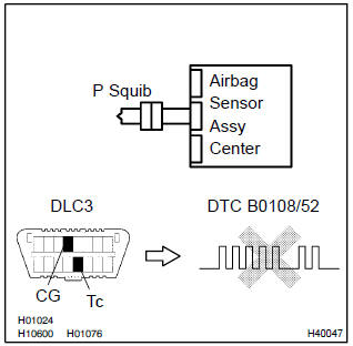
- Turn the ignition switch to lock.
- disconnect the negative (–) terminal cable from the battery, and wait at least for 90 seconds.
- connect the instrument panel passenger airbag assy connector.
- connect the negative (–) terminal cable to the battery, and wait at least for 2 seconds.
- turn the ignition switch to on, and wait at least for 20 seconds.
- clear the dtc stored in memory .
- turn the ignition switch to lock, and wait at least for 20 seconds.
- turn the ignition switch to on, and wait at least for 20 seconds.
- check the dtc .
Ok: dtc b0108/52 is not output.
Hint
: codes other than code b0108/52 may be output at this time, but they are not relevant to this check.

4 Use simulation method to check


Replace all srs components including the wire harness


Other materials:
Registering a Bluetooth® device
Before using the Bluetooth® audio/phone, it is necessary to register a Bluetooth®
device in the system. You can register up to 5 Bluetooth® devices.
How to register a Bluetooth® device
1 Press and select “Bluetooth*”
using .
2 Press and select “BT Pairing”
using .
A passkey w ...
Instrument panel/meter
Preparation
Sst
Recomended tools
Equipment
Seat
Preparation
Equipment
Theft deterrent & door lock
Preparation
Recomended tools
...
Air conditioning filter
The air conditioning filter must be changed regularly to maintain air conditioning
efficiency.
Removal method
1Turn the engine switch off.
2 Open the glove box. Slide off the damper.
3 Push in the glove box on the vehicle’s outer side to disconnect the claws.
Then pull out the glove box ...