Toyota Corolla (E120) 2002–2008 Repair Manual / Diagnostics / Sfi system / Knock sensor 1 circuit / Inspection procedure
Toyota Corolla (E120): Inspection procedure
Hint
: read freeze frame data using the hand-held tester or the obd ii scan tool. Freeze frame data records the engine conditions when a malfunction is detected. When troubleshooting, it is useful for determining whether the vehicle was running or stopped, the engine was warmed up or not, the air–fuel ratio was lean or rich, etc. At the time of the malfunction.
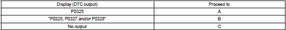
1 Read output dtc
- Clear the dtc.
- warm up the engine.
- run the engine at 3,000 rpm for 10 seconds or more.
- connect the hand–held tester or the obd ii scan tool to the dlc3.
- turn the ignition switch on and push the hand–held tester or the obd ii scan tool main switch on.
- select the item ”diagnosis / enhanced obd ii / dtc info / current codes”.
- read the dtcs.
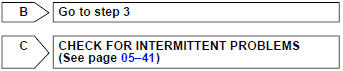
Result :

2 Inspect knock sensor
- Check the knock sensor installation.
Torque: 20 nvm (204 kgf·cm, 15 ftvlbf)


3 Check harness and connector(ecm – knock sensor)
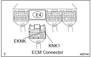
- Disconnect the e4 ecm connector.
- measure the resistance between terminals of the e4 ecm connector.
Standard:

- Reconnect the ecm connector.

4 Inspect ecm(knk1 voltage)
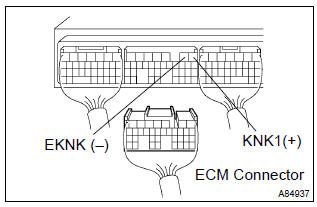
- Disconnect the e4 ecm connector.
- turn the ignition switch on.
- measure the voltage between terminals of the e4 ecm terminals.
Standard:

- Reconnect the ecm connector.

Check for intermittent problems
Notice
: fault may be intermittent. Check harness and connectors carefully.
5 Inspect knock sensor
- Remove the k1 knock sensor.
- measure the resistance between the terminals.
Standard:

- Reinstall the knock sensor.


Repair or replace harness or connector


Other materials:
On–vehicle inspection
1. Inspect front axle hub bearing
remove the front wheel.
separate the front disc brake caliper assy .
remove the front disc.
inspect the bearing backlash.
Using a dial indicator, check the backlash near the
center of the axle hub.
Maximum: 0.05 Mm (0. ...
Washer fluid
Add washer fluid in the following situations:
● A washer does not work.
● Vehicles without a multi-information display: The low windshield washer fluid
warning light (if equipped) comes on.
● Vehicles with a multi-information display: The warning message (if equipped) appear ...
Keys
The following keys are provided
with the vehicle.
Type A
Keys (without a wireless
remote control function)
Key number plate
Type B
Keys (with a wireless remote
control function)
Operating the wireless remote control
function
Key number plate
Type C
Electronic keys
Operating the sm ...