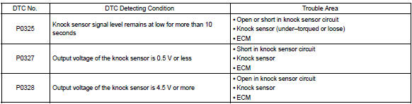
Toyota Corolla (E120) 2002–2008 Repair Manual / Diagnostics / Sfi system / Knock sensor 1 circuit / Circuit description
Toyota Corolla (E120): Circuit description
A flat type knock sensor (non–resonant type) has the structure that can detect the vibration in a wider band of frequency from about 6 khz to 15 khz and has the following features.
Knock sensors are fitted on the cylinder block to detect the engine knocking.
The sensor contains a piezoelectric element which generates a voltage when it becomes deformed, which occurs when the cylinder block vibrates due to knocking. If engine knocking occurs, the ignition timing is retarded to suppress it.
Hint
: if the ecm detects the dtc p0325, it enters the fail–safe mode in which the corrective retarded angle value is set to the maximum value.
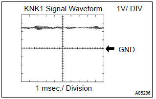
Reference: inspection using the oscilloscope.
- After warming up run the engine at 4,000 rpm, check the waveform between terminal knk1 and eknk of the ecm connector.
Monitor description
The knock sensor, located on the cylinder block, detects spark knock. When spark knock occurs, the sensor picks–up vibrates in a specific frequency range. When the ecm detects the voltage in this frequency range, it retards the ignition timing to suppress the spark knock.
The ecm also senses background engine noise with the knock sensor and uses this noise to check for faults in the sensor. If the knock sensor signal level is too low for more than 10 seconds, and if the knock sensor output voltage is out of normal range, the ecm interprets this as a fault in the knock sensor and sets a dtc.
Monitor strategy
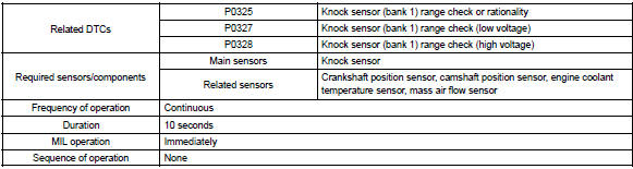
Typical enabling conditions
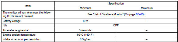
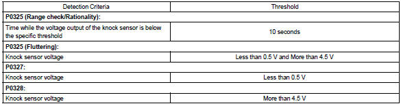
Typical malfunction thresholds
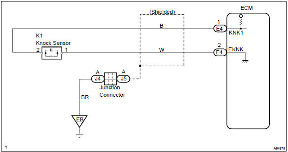
Wiring diagram


Other materials:
Overhaul
1. Remove speedometer drive (mtm) gear
Remove the speedometer drive (mtm) gear from the front
differential case.
2. Remove front differential ring gear
Place matchmarks on the front differential ring gear and
front differential case.
Remove the 8 bolts. Using a hamme ...
For safe driving
For safe driving, adjust the
seat and mirror to an appropriate
position before driving.
Correct driving posture
Adjust the angle of the seatback
so that you are sitting
straight up and so that you do
not have to lean forward to
steer.
Adjust the seat so that you
can depress the pedals fully ...
Inspection procedure
1 Check courtesy lamp switch
Check the courtesy switch, as shown in the illustration
and table.
Standard:
2 Check wire harness (integration relay door courtesy sw)
Disconnect the integration relay and door courtesy connectors.
check the continuity between th ...